
 WhatsApp: +86 16626708626
 Email:
  Phone: +86 16626708626
Description
3. Key Technical Specifications
| Parameter | Value |
|---|---|
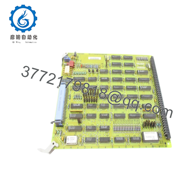
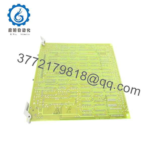
| Part Number | DS3800HRMD1C1B |
| Manufacturer | General Electric |
| Product Type | 8 KB RAM Board |
| Series | Speedtronic Mark IV DS3800 |
| Memory Capacity | 8 KB RAM |
| Memory Devices | EPROM / EEPROM based |
| Installation Type | Rack-mounted PCB |
| System Compatibility | GE Mark IV turbine control systems |
| Mounting Method | Screw-fixed with retention clips |
| Connector Type | Mixed male/female edge connectors |
| Operating Environment | Industrial turbine control cabinets |
| Cooling Method | Passive convection |
| Country of Origin | United States |
| Condition | New Surplus / Tested Refurbished depending on stock |
| Availability | Limited surplus inventory globally |
Technical references from current surplus market listings confirm the board as an 8 KB RAM board used within GE Mark IV turbine control architectures.
4. Product Introduction
The GE DS3800HRMD1C1B is an 8 KB RAM circuit board used in GE Speedtronic Mark IV turbine control systems. It provides temporary memory handling and data buffering functions for real-time turbine control operations inside Mark IV racks. The board is commonly found in gas turbine and power generation installations commissioned during the late 1980s and 1990s.
In field deployments of Mark IV systems, these memory boards typically remain reliable for decades if cabinet temperature and power quality stay within specification. Engineers still source this board mainly for lifecycle extension projects where a full Mark VI or Mark VIe migration is not yet economically justified.

- DS3800HRMD1C1B
- DS3800HRMD1C1B
5. Installation & Configuration Guide
Stage 1: Pre-Installation Preparation (Estimated Time: 10 Minutes)
⚠️ Safety First
- Notify operations and place the turbine or driven equipment into a verified safe shutdown condition.
- Lock out and tag out all control cabinet power sources.
- Wait at least 5 minutes for rack capacitors to discharge fully.
Tools Required
- Grounded ESD wrist strap
- PH1 screwdriver
- Fluke 115 multimeter
- Wire labels
- Smartphone for documentation photos
- Flashlight for rack inspection
Data Backup
- Export current turbine control configuration from the operator workstation if available.
- Record cabinet slot position and rack location.
- Photograph:
- DIP switch positions
- Jumper settings
- Connector orientation
- Adjacent board locations
- Document firmware revisions from associated controller modules.
❗ I’ve seen maintenance teams replace the correct board into the wrong slot during outage pressure. One quick rack photo before removal prevents hours of troubleshooting later.
Stage 2: Removing the Old Module (Estimated Time: 5 Minutes)
- Remove cabinet covers or front bezel panels carefully.
- Label all connected wiring and ribbon cables.
- Disconnect connectors evenly. Do not pry against the PCB.
- Release rack retention clips or locking tabs.
- Pull the module straight outward to avoid bending the backplane pins.
- Inspect:
- Backplane connectors
- Dust buildup
- Corrosion
- Heat discoloration
⚠️ Note: Keep the old module beside the rack until the replacement passes operational testing.
This matters more than people think. I’ve watched techs throw the old board into a scrap bin immediately, then realize two hours later the replacement had a jumper mismatch.
Stage 3: Installing the New Module (Estimated Time: 10 Minutes)
- Wear the grounded ESD strap before touching the board.
- Verify the exact model:
- DS3800HRMD1C1B
- Inspect the replacement board for:
- Rework marks
- Corrosion
- Broken traces
- UV yellowing
- Configuration Clone (Crucial):
- Match all DIP switches exactly
- Replicate jumper positions from photos
- Verify termination settings if applicable
- Insert the board evenly into the rack guides.
- Press firmly until the board seats fully into the backplane connector.
- Tighten mounting screws without over-torquing.
- Reconnect all wiring and ribbon cables.
Self-Checklist
- DIP switches match
- Jumpers match
- Connectors fully seated
- Rack tabs locked
- No loose hardware inside cabinet
❗ This is the most common rookie mistake, but experienced techs still get caught by it during outages. Take photos before removal. Every time.
Stage 4: Power-On & Testing (Estimated Time: 10–15 Minutes)
Pre-Power Check
- Use the multimeter to verify no shorts exist on the 24 V DC rail.
- Verify cabinet grounding continuity.
- Confirm no tools remain inside the enclosure.
Power-On Steps
- Energize the control rack only.
- Observe startup LED behavior.
- Green RUN LEDs indicate normal initialization
- Red fault LEDs indicate startup failure
- Connect the engineering workstation.
- Verify:
- Rack communication
- System diagnostics
- Memory recognition
- Reload configuration or logic if required.
- Perform dry-run I/O verification before enabling field outputs.
⚠️ Troubleshooting Note
- Solid red fault indication commonly points to firmware or configuration mismatch.
- No rack communication usually traces back to:
- Bent backplane pins
- Incorrect jumper settings
- Connector misalignment
I’ve personally seen a Mark IV outage stretched into two full shifts because someone installed a newer revision board without documenting the original jumper layout first.
6. Frequently Asked Questions (FAQ)
Q1: Can I hot-swap the DS3800HRMD1C1B under power?
No. Do not hot-swap this board.
The Mark IV platform predates many of the online maintenance protections found in newer DCS platforms. Pulling this board live can corrupt memory transactions or damage the backplane. Shut the rack down fully before replacement.
Q2: Is the DS3800HRMD1C1B obsolete?
Yes. GE Mark IV hardware is long obsolete from the OEM perspective.
Most available inventory today comes from:
- New surplus stock
- Plant spares
- Tested refurbished inventory
Availability changes constantly because many power plants continue extending Mark IV service life instead of performing full controls migrations.
Q3: Is this genuinely new or refurbished?
That depends on stock source.
Typical conditions include:
- New Original (factory surplus)
- New Surplus without original packaging
- Refurbished and load-tested
A serious supplier should provide:
- Actual photos
- Serial verification
- Test reports
- Boot test evidence
If a seller refuses to provide board photos, that’s a red flag.
Q4: Will I lose my programming logic when replacing this board?
Normally no, because this board primarily handles RAM and memory support functions inside the Mark IV architecture.
That said, never assume. Before removal:
- Back up the system
- Record firmware revisions
- Photograph jumper settings
I’ve seen projects where a technician swapped a newer revision module into an older rack and the system threw communication faults for nearly two days because firmware behavior changed slightly between revisions.
Q5: What should I verify before ordering a replacement?
Verify all of the following:
- Full part number including suffix
- Rack slot location
- Firmware revision compatibility
- Jumper and DIP settings
- Connector orientation
- Existing cabinet voltage
Even within GE DS3800 families, similar-looking boards can perform completely different functions.
Q6: Why are surplus prices sometimes lower than OEM historical pricing?
Because these boards are no longer in standard OEM production.
Pricing today depends on:
- Remaining inventory worldwide
- Plant shutdown recoveries
- Refurbishment availability
- Demand from turbine operators
A lower price does not automatically mean counterfeit hardware, but you should insist on electrical testing records and inspection photos.
Q7: What QC testing should a supplier perform before shipment?
Minimum acceptable testing should include:
- Visual inspection under magnification
- Serial and revision verification
- 500 V insulation resistance testing (>10 MΩ)
- Backplane communication testing
- Continuous powered burn-in testing for 24 hours
- ESD-safe packaging and anti-static sealing
For critical outages, request:
- Live power-up video
- LED startup sequence recording
- Test bench photos
- Firmware documentation
Test videos and photos should be available upon request. Keep these checks in mind and you’ll save yourself 90% of typical rework time.


