
 WhatsApp: +86 16626708626
 Email:
  Phone: +86 16626708626
Description
3. Key Technical Specifications
| Parameter | Value |
|---|---|
| Manufacturer | GE General Electric |
| Model Number | DS3800HRRB1B1A |
| Series | Mark IV Speedtronic |
| Product Type | Digital Relay I/O Board |
| Functional Description | Relay Output Digital I/O Interface |
| Memory Components | EEPROM and EPROM modules |
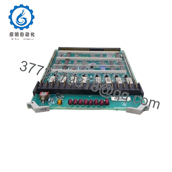
| LED Indicators | 8 red LEDs, 8 off-white LEDs, 1 yellow LED |
| Oscillator Components | 8 crystal oscillators |
| Connector Style | Male and female board connectors |
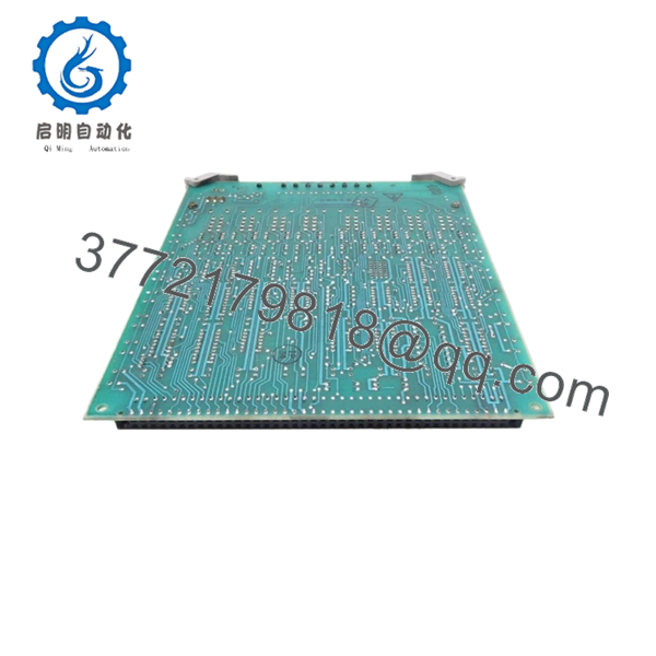
| Mounting Type | Rack-mounted PCB |
| Application | Turbine control digital relay interface |
| System Compatibility | GE Mark IV turbine systems |
| Operating Voltage | Typical 24 V DC cabinet environment |
| Operating Temperature | 0 °C to 60 °C |
| Storage Temperature | −20 °C to +85 °C |
| Humidity Rating | 5% to 95% non-condensing |
| Approximate Weight | 0.29 kg |
| PCB Coating | Industrial conformal-coated assembly |
| Warranty | 12 Months |
4. Product Introduction
The GE DS3800HRRB1B1A is a Digital Relay I/O Board designed for GE Mark IV Speedtronic turbine control systems. The board manages relay output handling and digital signal interfacing between the turbine controller and field-level control circuits used in gas and steam turbine applications.
In field maintenance work, this board is commonly replaced during forced outages or lifecycle extension projects where Mark IV infrastructure remains operational. Engineers typically retain the exact DS3800HRRB1B1A revision because relay timing behavior and interface characteristics can vary between revisions, especially in older turbine cabinets with undocumented modifications.

- DS3800HRRB1B1A
- DS3800HRRB1B1A
5. Installation & Configuration Guide
Stage 1: Pre-Installation Preparation (Estimated Time: 10 Minutes)
⚠️ Safety First
- Notify operations and obtain shutdown approval.
- Verify the turbine is in a safe maintenance condition.
- Apply lock out/tag out procedures.
- Disconnect cabinet power completely.
- Wait at least 5 minutes for capacitor discharge.
⚠️ Older Mark IV cabinets can retain residual DC voltage even after shutdown. Verify the rail with a meter before touching the rack.
Tools Required
- ESD wrist strap
- PH1 screwdriver
- Fluke 115 multimeter
- Wire labels
- Smartphone for reference photos
- Flashlight for cabinet inspection
Data Backup
- Export current turbine configuration data if available.
- Photograph all wiring and connector locations.
- Record cabinet slot location.
- Document any field-installed jumpers or modifications.
❗ This is where most avoidable mistakes begin. During outage pressure, technicians skip documentation, then spend hours tracing connectors later.
Stage 2: Removing the Old Module (Estimated Time: 5–10 Minutes)
- Remove the cabinet front cover.
- Label all connectors before removal.
- Disconnect wiring and ribbon cables carefully.
- Remove retaining hardware.
- Pull the board straight outward without twisting.
⚠️ Never pry the board sideways. Mark IV backplane connectors are old and fragile. One bent pin can create intermittent relay faults that are painful to diagnose.
- Inspect:
- Connector pins
- Edge contacts
- Dust buildup
- Heat discoloration
- Oxidation around solder joints
Field Reminder
Keep the original board beside the cabinet until startup is complete. I’ve seen engineers discover one undocumented jumper change only after several failed startups.
Stage 3: Installing the New Module (Estimated Time: 10 Minutes)
- Wear a grounded ESD strap before opening the anti-static bag.
- Verify the exact model number:
- DS3800HRRB1B1A
- Compare revision markings carefully.
Configuration Clone (Crucial)
- Replicate all jumper and connector configurations exactly.
- Verify relay output wiring orientation.
- Confirm grounding and shield termination practices match the original installation.
❗ This is the most common rookie mistake in legacy GE systems. One incorrect connector position can trigger false relay outputs or communication alarms throughout the turbine cabinet.
- Insert the board evenly into the rack guides.
- Ensure the board seats fully into the connector.
- Tighten retaining screws evenly.
- Reconnect all wiring carefully.
Self-Checklist
- Model verified
- Connector orientation confirmed
- Wiring secure
- Grounding verified
- Board fully seated
Stage 4: Power-On & Testing (Estimated Time: 15 Minutes)
Pre-Power Check
- Verify no shorts on the 24 V DC rail.
- Check cabinet grounding continuity.
- Inspect connector seating and ribbon cable routing.
Power-On Steps
- Energize the control rack only.
- Observe board LEDs during startup.
- Verify communication with the Mark IV controller.
- Confirm relay outputs respond correctly in diagnostics.
- Perform dry-run I/O testing before restoring field devices.
⚠️ If multiple relay outputs fail simultaneously after startup, inspect connector seating and backplane alignment before replacing additional boards.
SOP Testing Performed Before Shipment
Each DS3800HRRB1B1A unit undergoes:
- Inbound Inspection & Traceability
- OEM label verification
- Serial number inspection
- Anti-counterfeit checks
- Connector and solder inspection
- Live Functional Testing
- Tested on a genuine GE Mark IV rack
- Relay output simulation
- LED status verification
- Continuous thermal load test exceeding 24 hours
- Electrical Parameter Testing
- 500 V insulation resistance test (>10 MΩ)
- Ground continuity verification
- Power rail stability testing
- Firmware & Configuration Verification
- EPROM/EEPROM inspection
- Jumper documentation
- Revision photo archive
- Final QC & Packaging
- Anti-static ESD packaging
- Bubble wrap and reinforced export carton
- QC sign-off with inspection date
Test videos and inspection photos are available upon request.
6. Frequently Asked Questions (FAQ)
Q1: Can the DS3800HRRB1B1A be hot-swapped?
No.
The Mark IV platform was not designed for routine hot-swapping of relay I/O boards. Pulling this board live risks backplane damage and unstable relay output conditions.
Shut the cabinet down fully before replacement.
Q2: Is the DS3800HRRB1B1A obsolete?
Yes. The Mark IV Speedtronic platform is considered legacy equipment and has been out of active OEM production for many years. Most inventory available today comes from surplus industrial stock or refurbishment channels.
Many plants still operate Mark IV systems because replacing turbine controls requires major outage planning, validation, and commissioning work.
Q3: Is this genuinely new hardware?
This listing refers to New Original / New Surplus inventory unless otherwise specified.
That generally means:
- No previous field installation
- OEM-manufactured hardware
- Long-term industrial spare storage
Due to age, external packaging may show shelf wear. Every board is inspected for oxidation, connector damage, and storage-related deterioration before shipment.
Q4: What does this board actually do inside the Mark IV system?
The DS3800HRRB1B1A manages relay output and digital I/O interface functions within the turbine control cabinet. It processes control signals between the Mark IV controller and field relay circuits used for sequencing and protective logic.
Q5: What installation mistake causes the most downtime?
Connector misalignment and ESD damage.
I’ve watched technicians force boards into aging backplanes during outage pressure. The system powered up, but intermittent relay failures started immediately because one connector pin folded underneath the board edge.
Take your time seating the board correctly.
Q6: Will replacing this board erase turbine logic?
Normally no. The DS3800HRRB1B1A primarily handles digital relay interfacing rather than storing primary turbine sequencing logic.
Still, always back up the control system before maintenance. I’ve seen undocumented field modifications disappear because nobody documented the cabinet beforehand.
Q7: Why are surplus Mark IV boards still expensive?
Because turbine downtime is expensive.
A forced outage waiting on one relay I/O board can cost far more in lost generation revenue than the hardware itself. Plants continue paying premium prices for verified spare inventory with documented testing and immediate availability.
❗ I once watched an engineer install a replacement Mark IV board during winter maintenance without an ESD strap. The board powered up briefly, then failed permanently within seconds. That single mistake extended the outage another full shift.
Keep these checks in mind and you’ll save yourself 90% of typical rework time.


