
 WhatsApp: +86 16626708626
 Email:
  Phone: +86 16626708626
Description
3. Key Technical Specifications
| Parameter | Value |
|---|---|
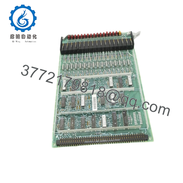
| Model Number | DS3800HSCC1D1D |
| Manufacturer | GE General Electric |
| Product Type | Non-Isolated Input Board |
| Series | GE Speedtronic Mark IV DS3800 |
| Primary Function | Input signal processing |
| Input Voltage | 28 VDC |
| Input Isolation | Non-isolated |
| Circuit Feature | Buffer decoder architecture |
| LED Indicators | 16 onboard LEDs |
| Integrated Circuits | 19 onboard ICs |
| Mounting Type | Rack-mounted PCB |
| Connector Style | Front edge and backplane connector |
| Product Status | Legacy / Discontinued |
| Application | Turbine and machine control systems |
4. Product Introduction
The GE DS3800HSCC1D1D is a Non-Isolated Input Board used in GE Speedtronic Mark IV turbine control systems. It operates on a 28 VDC input architecture and processes field signal inputs through onboard decoder circuitry for communication with the Mark IV control environment.
In field deployments of Mark IV systems, these input boards typically survive for years with little attention until cabinet heat, contamination, or connector wear starts creating intermittent signal problems. I have seen technicians chase phantom turbine trips for hours when the root cause was a deteriorating input board edge connector rather than a failed field device. Because Mark IV hardware is long out of production, most sites maintain spare inventory.

- DS3800HSCC1D1D
5. Installation & Configuration Guide
Stage 1: Pre-Installation Preparation (Estimated Time: 10 minutes)
⚠️ Safety First: Notify operations of planned downtime. Verify turbine shutdown and process safe state. Apply lock out/tag out procedures. Wait 5 minutes minimum for discharge of cabinet capacitors.
Tools Required
- ESD wrist strap
- PH1 screwdriver
- Fluke 115 multimeter
- Wire labels
- Smartphone for photos
- Flashlight
Data Backup
- Export available configuration files.
- Record active faults and alarm history.
- Photograph all cable routing.
- Photograph jumper and connector locations.
- Record board revision identifiers.
⚠️ Mark IV systems often contain undocumented modifications from previous outages. Never trust drawings alone.
Stage 2: Removing the Old Module (Estimated Time: 5–10 minutes)
Steps:
- Remove cabinet access covers.
- Label all cable positions.
- Disconnect connectors carefully.
- Release retaining hardware.
- Pull board straight out using extraction hardware.
- Inspect backplane connector condition.
Inspect:
- Bent pins
- Dust buildup
- Heat discoloration
- Corrosion
- Connector wear
⚠️ Keep the old board nearby.
I’ve watched maintenance teams dispose of a failed board immediately, only to realize later that undocumented jumper settings were gone with it.
Stage 3: Installing the New Module (Estimated Time: 5 minutes)
Steps:
- Wear grounded ESD protection.
- Verify exact model DS3800HSCC1D1D.
- Configuration Clone (Crucial): Replicate all jumper settings from photographs.
- Insert board evenly into guide rails.
- Verify full seating against backplane connectors.
- Reconnect all wiring.
Self-Checklist:
- Jumpers verified
- Wiring secure
- Connector seating confirmed
- Retainers locked
❗This is the most common rookie mistake, but it happens constantly. Take a picture before you pull it. I can’t stress this enough.
Stage 4: Power-On & Testing (Estimated Time: 10–15 minutes)
Pre-Power Check
Verify no short exists on the 24 V rail using a multimeter.
Power-up sequence:
- Energize cabinet only.
- Observe board LED activity.
- Verify startup indicators.
- Connect engineering workstation.
- Check input status diagnostics.
- Run dry I/O verification.
LED guidance:
- Expected LED activity indicates signal processing
- Unexpected LED patterns may indicate input faults
⚠️ Troubleshooting Note: If multiple field inputs appear active simultaneously, inspect grounding and remember this is a non-isolated input board.
I once watched a winter startup consume an entire shift because electrical noise created misleading input indications. The board was fine. Cabinet grounding was not.
6. Frequently Asked Questions (FAQ)
Q1. Can I hot-swap this module?
No.
Do not hot-swap the DS3800HSCC1D1D. Mark IV hardware was never designed for live insertion. Removing a board under power risks backplane damage and intermittent control faults.
Kill power first.
Q2. Is DS3800HSCC1D1D obsolete?
Yes.
This board belongs to the GE Mark IV platform and is considered legacy hardware. Current inventory typically comes from surplus stock or refurbished tested units because OEM manufacturing ended years ago. Available market inventory varies significantly.
Q3. What does “non-isolated input” actually mean?
This matters more than many technicians realize.
Non-isolated inputs share electrical reference paths. Noise, grounding problems, and improper shielding can create false indications.
I’ve seen technicians replace three boards before discovering a grounding problem.
Always inspect shielding termination and common reference points.
Q4. Will I lose logic if I remove this board?
Normally no.
The DS3800HSCC1D1D handles input acquisition functions. Main control logic usually resides elsewhere in the Mark IV architecture.
Still back everything up before shutdown.
Assumptions create expensive outages.
Q5. Why does pricing vary so much?
Legacy inventory behaves differently than current-production PLC hardware.
Current price variation usually depends on:
- New surplus versus refurbished condition
- Test documentation included
- Warranty period
- Inventory source
- Hardware revision availability
Recent market listings showed inventory ranging from approximately 2,400 to over 4,400 depending on condition and supplier source.
Q6. How are these boards tested before shipment?
Standard workflow:
Inbound Inspection & Traceability
- Source verification and serial checks
- Anti-counterfeit inspection
- Corrosion inspection
- Visual inspection for rework marks and UV aging
Live Functional Testing
- Testing on compatible GE hardware where available
- Power-up verification
- Communication checks
- I/O simulation
- Continuous runtime >24 hours
Electrical Testing
- 500 V insulation resistance test (>10 MΩ)
- Ground continuity verification
- Hipot testing if applicable
Firmware & Configuration Verification
- Revision recording
- Jumper documentation
Final QC
- QC sign-off
- ESD packaging
- Bubble wrap protection
- Heavy-duty corrugated carton
Test videos and photos are available upon request.
Q7. What installation mistake causes the most downtime?
❗Ignoring grounding and jumper documentation.
Because this board uses a non-isolated design, technicians often assume strange input behavior means board failure.
I once watched an engineer replace hardware repeatedly while a bad shield ground created the entire problem.
Keep these checks in mind and you’ll save yourself 90% of typical rework time.


