
 WhatsApp: +86 16626708626
 Email:
  Phone: +86 16626708626
Description
Key Technical Specifications
| Parameter | Specification |
| Component Category | Microprocessor Interface Board |
| System Compatibility | GE Speedtronic Mark IV Gas/Steam Turbine Control |
| Firmware Architecture | Socketed EPROM/PROM support |
| Revision Level | 1C1E (Enhanced logic revision) |
| Operating Voltage | +5 VDC / +/- 15 VDC from Rack Backplane |
| I/O Connectivity | Card edge connector (Gold-plated) |
| Signal Processing | Digital logic and display driver interface |
| Storage Temperature | -40 to +85°C (-40 to 185°F) |
| Operating Temperature | 0 to 60°C (32 to 140°F) |
Product Introduction
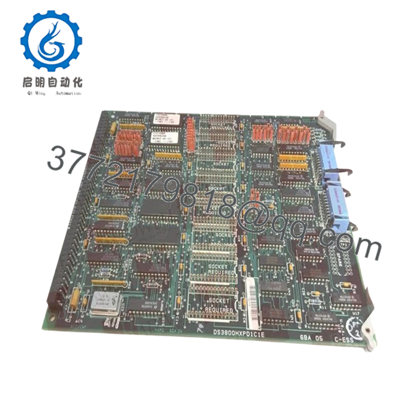
The GE DS3800HXPD1C1E is a specialized microprocessor-based interface board designed for the Speedtronic Mark IV control system. Its primary role is managing data flow between the control processors and the operator display units. As part of the HXPD family, this card handles the complex logic required to translate system diagnostic data into human-readable information, ensuring operators have real-time visibility into turbine performance.
This specific revision, 1C1E, represents one of the final iterations of the Mark IV display logic, offering improved stability over older revisions. For facilities still running Mark IV systems, maintaining a spares inventory of HXPD boards is critical, as these are often the first point of failure in operator interface issues. This board is a “New Surplus” unit, ensuring that the components—particularly the critical logic chips—have not been subjected to the thermal stress of decades-long continuous operation.

- DS3800HXPD1C1E
Installation & Configuration Guide
Stage 1: Pre-Installation Preparation (Estimated Time: 15 mins)
- ⚠️ Safety First: Ensure the Mark IV control cabinet is properly isolated. Even though this is a logic board, power surges during insertion can cause system-wide trips.
- Tools Required: Grounding wrist strap (ESD), IC extraction tool (if firmware swap is needed), and a bright flashlight for backplane inspection.
- Firmware Verification: Check the socketed chips on your existing board. You may need to migrate the original EPROMs to the new DS3800HXPD1C1E to maintain site-specific display configurations.
Stage 2: Removing the Old Module
- Power down the controller rack containing the HXPD card.
- Photograph the jumpers and DIP switches. The HXPD series often uses these to define display scaling and node identification.
- If there are ribbon cables attached to the front or sides of the board, carefully disconnect them by pulling on the connector housing, not the cable itself.
- Gently unseat the card from the backplane and slide it out of the card guides.
Stage 3: Installing the New Module (Estimated Time: 20 mins)
- DIP Switch Mirroring: Match the settings on the new board to the old one exactly. This is the most common reason for “Display Timeout” errors post-installation.
- Firmware Migration (Critical): If the new board does not come with your site-specific firmware, carefully move the EPROM chips from the old board to the new one. Ensure correct orientation (notch alignment).
- Insert the board into the rails and push firmly until you feel the card edge connector lock into the backplane.
- Reconnect any ribbon cables removed in Stage 2.
- Self-Checklist: [ ] DIP switches match, [ ] EPROMs seated/oriented correctly, [ ] Cables secured.
Stage 4: Power-On & Testing
- Restore power to the rack.
- Monitor the “Run” or “Status” LEDs. A steady green status usually indicates the microprocessor has initialized successfully.
- Check the operator interface. If the display remains blank but the board has power, suspect a mismatch in the baud rate or node address set via the DIP switches.
- Perform a function test by cycling through several display pages to ensure data refresh rates are normal.
Frequently Asked Questions (FAQ)
Q: Can I use a 1C1E revision to replace an older 1A1A version?
A: Yes. GE designed these revisions to be backward compatible. The 1C1E includes circuit refinements that handle electronic noise better than the 1A or 1B versions. However, you must ensure you move your original firmware chips to the new board to maintain compatibility with your specific turbine’s logic.
Q: Why is my display showing “Garbage” characters after installing the new board?
A: This is almost always a jumper or DIP switch mismatch. The HXPD board uses these switches to define how it parses data for the display. Double-check your settings against the old board. If they match, ensure the socketed EPROMs are pressed firmly into their sockets.
Q: Is it safe to leave the system powered on while I swap this board?
A: No. While some modern DCS systems support hot-swapping, the Mark IV architecture is from an era where “Live Insertion” could cause a bus contention or a voltage drop that crashes the entire control processor. Always kill power to the rack.
Q: Does this board come with the firmware chips included?
A: Most “New Surplus” boards are sold as the base hardware without the site-specific EPROMs. Since the code on these chips is unique to your turbine’s configuration, we recommend migrating your existing chips to this new hardware.
Q: My old board has visible scorch marks around some resistors. Will this board solve that?
A: Scorched resistors on an HXPD board usually indicate an overvoltage condition or a short in the display cable. While this new board will replace the damaged components, I strongly recommend checking your 24V/12V power supply levels before powering up the new board to prevent the same failure.


