
 WhatsApp: +86 16626708626
 Email:
  Phone: +86 16626708626
Description
3. Key Technical Specifications
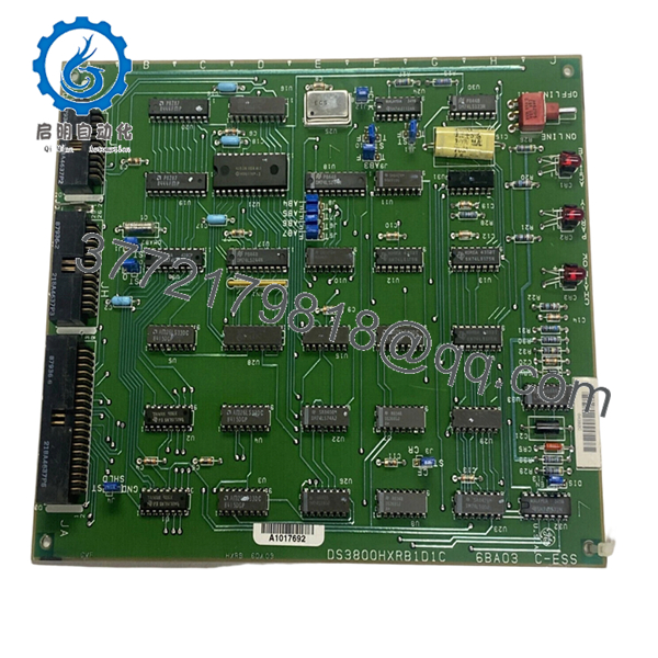
Field inventories for legacy GE Mark IV boards vary by production revision and installed component population. Verify exact board markings and hardware revision before installation. DS3800HXRB is identified as a C Bus Receiver Board used within GE Mark IV turbine controls.
| Parameter | Value |
|---|---|
| Manufacturer | GE |
| Model | DS3800HXRB |
| Product Family | DS3800 Series |
| System Platform | GE Mark IV Speedtronic |
| Product Type | C Bus Receiver Board |
| Communication Role | C Bus signal receiver |
| Board Features | Jumpers, LEDs, connector interfaces |
| Operating Temperature | −30 °C to +55 °C |
| Mounting Style | Rack-installed PCB |
| Firmware Dependency | Revision sensitive |
| Connector Type | Multi-pin board connectors |
| Condition | New Original / New Surplus |
The board includes multiple integrated circuits, jumper settings, LEDs, and connector assemblies used for signal routing and communication functions.
4. Product Introduction
The GE DS3800HXRB is a C Bus Receiver Board used in GE Mark IV Speedtronic gas and steam turbine control systems. It processes and receives communication signals inside the control architecture and exchanges information through the Mark IV backplane structure.
In field deployments of aging Mark IV systems, replacement boards like DS3800HXRB are often kept as strategic spare inventory because shutdown windows are measured in hours, not weeks. Revision matching matters more than board appearance.

- DS3800HXRB
5. Installation & Configuration Guide
Stage 1: Pre-Installation Preparation (Estimated: 10 minutes)
⚠️ Safety First: Notify operations of downtime. Verify process shutdown. Apply lockout/tagout procedures and wait 5 minutes for power supply discharge.
Tools Required
- ESD wrist strap
- PH1 screwdriver
- Fluke 115 multimeter
- Wire labels
- Smartphone
- ESD work mat
- Flashlight
Data Backup
- Export controller configuration where possible
- Record cabinet and slot positions
- Photograph all DIP switches and jumpers
- Photograph cable routing
- Document board labels and revisions
Stage 2: Removing the Old Module (Estimated: 5–10 minutes)
Steps:
- Remove cabinet covers
- Label every cable and connector
- Disconnect wiring carefully
- Release retention hardware
- Pull board straight out
⚠️ Note: Keep the original board nearby until successful startup verification.
Inspect:
- Backplane condition
- Bent connector pins
- Dust buildup
- Corrosion
- Heat damage
Stage 3: Installing the New Module (Estimated: 10 minutes)
Steps:
- Attach ESD strap
- Verify exact model: DS3800HXRB
- Configuration Clone (Crucial):
- Match jumper positions
- Match DIP settings
- Match addressing selections
- Verify bus settings
This is the most common rookie mistake, but it happens constantly. Take a picture before you pull it. I can’t stress this enough.
- Install board evenly into guide rails
- Seat board fully
- Lock retention hardware
- Reconnect all wiring
Self-Checklist
- DIPs match
- Wiring secure
- Board seated correctly
- Locking hardware secured
Stage 4: Power-On & Testing (Estimated: 10–15 minutes)
Pre-Power Check
Use a multimeter and verify no short exists on power rails.
Power sequence:
- Energize rack only
- Observe LED behavior
- Verify startup sequence
- Connect engineering workstation
- Confirm communication status
- Restore saved configurations if needed
- Run dry I/O tests
LED guidance:
- Green RUN = expected behavior
- Red ERR = fault condition
⚠️ Troubleshooting Note: Immediate communication faults after startup frequently indicate board revision conflicts.
I once watched technicians replace three boards before discovering one replacement revision changed communication behavior enough to trigger alarms.
Technical Pitfall & Survival Guide
❗ Firmware Revision Mismatch
Issue:
Board revisions and firmware generations do not always behave identically.
Avoidance:
Document board labels and firmware identifiers before removal.
I’ve seen systems remain offline for two days because a replacement revision altered communication timing enough to trigger “Communication Timeout” alarms.
❗ DIP Switch / Jumper Misconfiguration
Issue:
Factory settings rarely match field settings.
Avoidance:
Take photographs before removal.
This is the most common rookie mistake. It happens constantly.
❗ Terminal Block / Wiring Differences
Issue:
Connector functions occasionally vary by revision.
Warning:
Even similar GE DS3800 assemblies can change signal assignments. Verify manuals. Never wire from memory.
❗ Power Draw Specifications
Issue:
Older power supplies frequently operate near limits.
Avoidance:
Calculate rack loading and maintain a 20% power margin.
A replacement board may not be the actual issue. I’ve seen overloaded supplies create startup failures that looked exactly like communication faults.
❗ Electrostatic Discharge (ESD)
Issue:
Board damage before installation.
Avoidance:
Wear a grounded strap and work on ESD surfaces.
I once watched an engineer handle a board during winter without protection. Powered once. Never again. Expensive lesson.
Keep these checks in mind and you’ll save yourself 90% of typical rework time.
Quality Inspection & Functional Verification SOP
1. Inbound Inspection & Traceability
- OEM packing verification
- Serial number inspection
- Anti-counterfeit checks
- Visual inspection:
- scratches
- corrosion
- rework marks
- UV discoloration
- Accessory verification
2. Live Functional Testing
Test equipment:
- Genuine GE Mark IV rack
- Simulation environment
- Fluke 115 multimeter
Testing:
- Power-on diagnostics
- LED startup verification
- Communication handshake checks
- Signal simulation testing
- Continuous 24-hour load operation
- Thermal monitoring
Test reports generated.
Test photos and videos available upon request.
3. Electrical Parameter Testing
- Insulation resistance:
- 500 V Megger
- Greater than 10 MΩ
- Ground continuity verification
- Hipot testing where applicable
4. Firmware Documentation
- Record installed revisions
- Photograph DIP settings
- Photograph jumper settings
5. Final QC & Packaging
- QC sign-off
- Anti-static ESD packaging
- Bubble wrap protection
- Heavy-duty corrugated boxing
- QC labeling with inspection date
Verified fully functional under load testing.
6. Frequently Asked Questions (FAQ)
Q1: Can I hot-swap this module?
No.
GE Mark IV systems were not designed around modern hot-swap architecture. Pulling boards live risks backplane damage and unstable system behavior.
Power down first.
Q2: Is DS3800HXRB obsolete?
Yes.
DS3800HXRB is discontinued and generally available only from surplus inventory or tested stock channels.
Q3: Is this genuinely new?
Available inventory usually falls into:
- New Original / New Surplus
- Refurbished and tested
Always request actual inventory photos before ordering.
Q4: What exactly does DS3800HXRB do?
It functions as a C Bus Receiver Board and handles communication signal reception within GE Mark IV architecture.
Q5: Will I lose logic if I remove this board?
Usually no.
Logic commonly resides elsewhere in the Mark IV control architecture, but assumptions create downtime. Backup system information before touching hardware.
Q6: Why are obsolete board prices inconsistent?
Availability drives pricing.
These boards often come from shutdown inventory, spare stock reductions, and canceled projects.
Q7: Is the module tested before shipment?
Yes.
Testing includes communication verification, startup diagnostics, insulation testing, and extended operational load testing before QC release.


