
 WhatsApp: +86 16626708626
 Email:
  Phone: +86 16626708626
Description
3. Key Technical Specifications
- Function: 12-bit analog-to-digital conversion for turbine signals
- System Compatibility: GE Mark IV Speedtronic turbine control system
- Input Type: Analog signals (field instrumentation: pressure, temperature, vibration)
- Resolution: 12-bit A/D conversion
- Configuration: Jumper-selectable range, parity, oscillator settings
- Auxiliary Board Support: Optional DS3800DADB capacitor expansion module
- Indicators: Onboard LED status indication
- Test Points: COM / SYNC / AOUT diagnostic points
- Power Supply: Backplane powered (5 V / 24 V typical Mark IV rails)
- Mounting: Rack-mounted Eurocard PCB with extractors
- Operating Temperature: 0 to +60°C typical (cabinet controlled)
- Weight: ~0.3–0.5 kg
4. Product Introduction
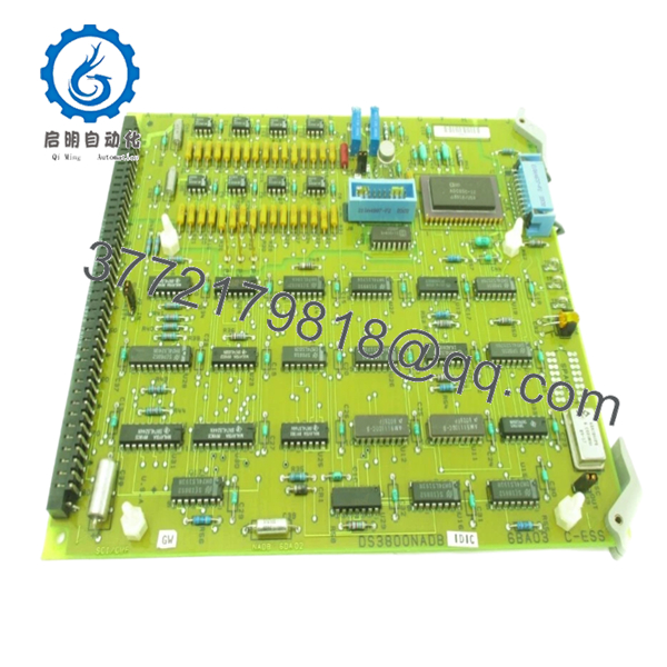
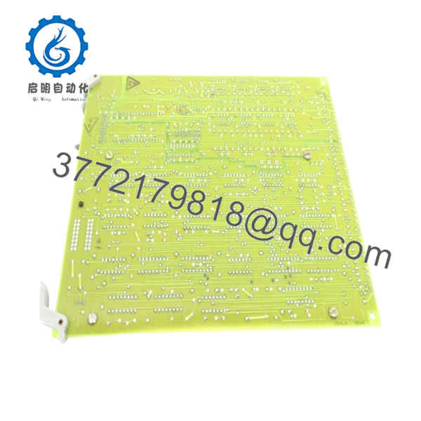
The GE DS3800NADB1D1C is a 12-bit analog-to-digital converter board used in the Mark IV Speedtronic turbine control system. It converts field analog signals into digital data for processing by the control CPU.
In real-world turbine control systems, this board sits directly in the signal acquisition path. The jumper-configurable design allows adjustment of input ranges and timing parameters, but it also introduces risk during replacement. Unlike modern PLC I/O, there is no auto-detection—configuration must match exactly.
5. Installation & Configuration Guide
Stage 1: Pre-Installation Preparation (Estimated: 10 minutes)
- ⚠️ Safety First:
Shutdown turbine/system, apply lockout/tagout. Wait minimum 5 minutes for discharge. - Tools Required:
ESD strap, PH1 screwdriver, multimeter, wire labels, smartphone - Data Backup:
- Photograph jumper positions (J1, J2, J3) — critical
- Record analog signal ranges (4–20 mA, ±10 V)
- Document slot location and wiring
Stage 2: Removing the Old Module (Estimated: 5–10 minutes)
- Locate DS3800NADB1D1C in the rack.
- Label all signal wiring carefully.
- Disconnect connectors—avoid stressing aged terminals.
- Release retaining clips.
- Pull board straight out to protect backplane pins.
- Inspect connector for oxidation or debris.
- ⚠️ Note: Keep the old board for jumper reference.
Stage 3: Installing the New Module (Estimated: 10 minutes)
- Wear ESD protection.
- Verify exact model: DS3800NADB1D1C (revision matters).
- Configuration Clone (Critical):
- Replicate all jumper settings (J1 range, J2 parity, J3 oscillator).
- Insert board into correct slot, ensure alignment.
- Seat firmly using extractor levers.
- Reconnect wiring exactly as labeled.
- Self-Checklist:
- Jumpers match original
- Wiring correct
- Board fully seated
- No bent pins
Stage 4: Power-On & Testing (Estimated: 10–15 minutes)
- Pre-Power Check:
Verify no shorts on input channels using multimeter. - Power-On Steps:
- Power rack only.
- Check LED status (basic health indication).
- Monitor analog values in control system.
- Compare readings with baseline values.
- Inject known signal (loop calibrator recommended).
- ⚠️ Troubleshooting Note:
- Incorrect readings → jumper mismatch
- No signal → wiring or seating issue
- Noise → grounding/shielding problem

- DS3800NADB1D1C
- DS3800NADB1D1C
6. Frequently Asked Questions (FAQ)
Q1: Can I hot-swap this board?
No. Mark IV hardware does not support hot-swapping. Doing so risks backplane damage and system trips.
Q2: Is DS3800NADB1D1C obsolete?
Yes. This is legacy Mark IV hardware. Availability is limited to surplus or refurbished stock.
Q3: What’s the difference between A1A, B1B, and D1C revisions?
Mostly hardware revisions—component changes, jumper behavior, or minor circuit improvements. Functionally similar, but not always interchangeable. Always match the exact suffix.
Q4: Will I lose control logic during replacement?
No. Logic resides in processor boards. However, bad A/D data will immediately affect control behavior.
Q5: Why are readings incorrect after replacement?
Most common cause is jumper mismatch. Second is grounding or signal scaling differences.
Q6: Why is surplus pricing lower than OEM?
You’re buying discontinued inventory without OEM lifecycle support. Pricing reflects supply scarcity and condition—not factory production cost.
SOP Quality Transparency
1. Inbound Inspection & Traceability
- Verified part number and revision markings
- Visual inspection: no corrosion, no rework, no connector wear
- Jumper integrity checked
- Traceability recorded
2. Live Functional Testing
- Tested on Mark IV-compatible rack simulator
- Analog signal injection using Fluke 724 calibrator
- Verified 12-bit conversion accuracy across full range
- 24-hour continuous load test with thermal monitoring
- Test reports available upon request
3. Electrical Parameter Testing
- Insulation resistance: >10 MΩ @ 500 V Megger
- Ground continuity verified
- Stable voltage rail verification
4. Firmware & Configuration Verification
- Hardware jumper configuration documented
- No firmware dependency (hardware-driven board)
5. Final QC & Packaging
- QC sign-off with traceable ID
- ESD-safe packaging
- Shock-resistant industrial boxing
Technical Pitfall & Survival Guide
❗ 1. Jumper Misconfiguration (Most Common Failure)
- Issue: Wrong input range or timing configuration
- Avoidance: Photograph jumpers before removal
- Field reality: This causes more downtime than actual hardware failure
❗ 2. Revision Mismatch Assumptions
- Issue: Assuming A1A = D1C compatibility
- Avoidance: Match full part number including suffix
- I’ve seen systems reject boards that “look identical”
❗ 3. Signal Scaling Errors
- Issue: Incorrect engineering unit conversion
- Avoidance: Verify scaling in control logic and hardware
- Real case: Temperature reading off by 20% due to mismatch
❗ 4. Aging Backplane Connectors
- Issue: Intermittent signal loss
- Avoidance: Inspect and reseat carefully
- Mark IV racks are decades old—mechanical wear matters
❗ 5. ESD Damage During Handling
- Issue: Latent board failure hours after startup
- Avoidance: Always use ESD protection
- I’ve personally seen boards fail after “successful” commissioning


