
 WhatsApp: +86 16626708626
 Email:
  Phone: +86 16626708626
Description
3. Key Technical Specifications
| Parameter | Value |
|---|---|
| Manufacturer | GE General Electric |
| Model Number | DS3800NBIC1J1G |
| Product Series | Speedtronic Mark IV |
| Functional Description | Bridge Interface Circuit Board |
| Product Type | Interface PCB Assembly |
| Application | Gas and steam turbine control systems |
| System Compatibility | GE Mark IV Speedtronic racks |
| Integrated Circuits | 26 onboard ICs |
| Transistor Count | 15 transistors |
| Resistance Networks | 7 onboard resistor networks |
| Test Points | 24 diagnostic test points |
| Indicator Type | Single orange LED |
| Connector Type | Edge-mounted backplane connector |
| Jumper Configuration | Configurable blue jumper pins |
| Mounting Method | Rack-mounted PCB |
| Operating Environment | Industrial turbine control cabinet |
| Firmware Dependency | Verify compatibility with installed Mark IV revision |
| Availability | Limited surplus inventory |
| Typical Lead Time | 3–7 business days depending on stock |
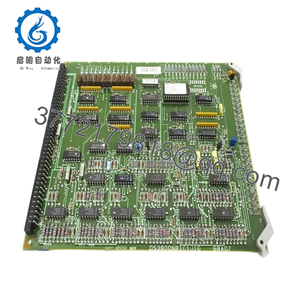
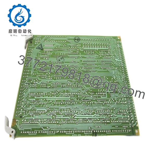
The DS3800NBIC1J1G is identified as a GE Mark IV bridge interface circuit board used in Speedtronic turbine control systems for interface communication and signal handling functions within gas and steam turbine applications.
4. Product Introduction
The GE DS3800NBIC1J1G is a bridge interface PCB designed for GE Speedtronic Mark IV gas and steam turbine control systems. The board operates as an interface circuit assembly inside the Mark IV architecture, supporting communication and signal interaction between connected turbine control subsystems.
In operating turbine facilities, boards like the DS3800NBIC1J1G are typically maintained as strategic spare inventory because replacing a failed interface board is significantly faster and lower risk than redesigning legacy cabinet architectures. Plants still operating Mark IV systems often prioritize direct replacement to minimize commissioning risk and outage duration.
5. Installation & Configuration Guide
Stage 1: Pre-Installation Preparation (Estimated Time: 10 Minutes)
⚠️ Safety First
- Notify operations and maintenance personnel of the planned outage.
- Verify the turbine is in a safe shutdown condition.
- Apply lock out/tag out (LOTO) procedures to all cabinet power sources.
- Wait a minimum of 5 minutes for capacitor discharge.
Tools Required
- Grounded ESD wrist strap
- PH1 screwdriver
- Fluke 115 multimeter or equivalent
- Wire labels
- Smartphone for cabinet photos
- Flashlight for rack inspection
Data Backup
- Record rack slot location and board orientation.
- Photograph all jumper positions and connector layouts.
- Label associated wiring carefully before removal.
- Document current alarm conditions and cabinet LED states.
❗ Take photos before removing the board. I’ve watched experienced technicians reinstall perfectly good boards backward after a 12-hour outage shift because multiple slots looked nearly identical inside the cabinet.
Stage 2: Removing the Old Module (Estimated Time: 5–10 Minutes)
- Open cabinet access panels carefully.
- Verify all associated rack power is isolated.
- Label and disconnect connectors methodically.
- Release retention clips or mounting hardware.
- Pull the PCB straight out evenly to avoid connector damage.
- Inspect the backplane for:
- Bent pins
- Heat discoloration
- Dust contamination
- Connector oxidation
⚠️ Important Note
Keep the removed board beside the cabinet during commissioning. Even failed modules are valuable references for jumper settings and revision identification.
Stage 3: Installing the New Module (Estimated Time: 10 Minutes)
Installation Steps
- Wear grounded ESD protection before touching the PCB.
- Verify the replacement model exactly matches:
- DS3800NBIC1J1G
- Compare hardware revision markings with the original board.
- Configuration Clone (Crucial):
- Replicate all jumper settings exactly
- Verify any configurable interface options
- Confirm termination settings if applicable
- Align the PCB carefully with the rack guides.
- Insert evenly until fully seated in the backplane connector.
- Secure retention hardware.
- Reconnect all connectors and wiring.
Self-Checklist
- Correct model verified
- Jumpers matched
- Board seated fully
- Connectors secure
- Retention hardware locked
❗ Partial seating is one of the worst intermittent faults on Mark IV racks. The LEDs may look normal while communication errors appear randomly across the system.
Stage 4: Power-On & Testing (Estimated Time: 10–15 Minutes)
Pre-Power Check
- Verify no short exists on cabinet DC rails.
- Confirm cabinet grounding continuity.
- Inspect for loose hardware inside the cabinet.
Power-On Steps
- Energize the rack first before enabling field devices.
- Observe startup LEDs on the DS3800NBIC1J1G.
- Verify normal communication with associated control boards.
- Check diagnostic alarms through the HMI or engineering workstation.
- Perform dry-run I/O testing before turbine startup.
⚠️ Troubleshooting Note
If communication faults appear immediately after startup:
- Recheck jumper positions
- Verify full backplane seating
- Confirm firmware revision compatibility
- Inspect connector oxidation
- Verify correct rack slot placement
I’ve seen one replacement interface board trigger intermittent “Communication Timeout” alarms for nearly two days because the replacement revision handled signal timing slightly differently than the original hardware.
Quality Control & Testing Procedure
1. Inbound Inspection & Traceability
Each DS3800NBIC1J1G board undergoes:
- OEM label verification
- Serial number traceability inspection
- Anti-counterfeit checks
- Visual inspection for corrosion, UV yellowing, solder rework, and damaged traces
- Connector and edge-contact inspection
2. Live Functional Testing
Testing is performed using GE Mark IV-compatible rack hardware whenever available.
Procedures include:
- Controlled power-up testing
- LED startup verification
- Interface communication testing
- Signal continuity checks
- Continuous energized runtime testing exceeding 24 hours with thermal monitoring
Test photos and startup videos are available upon request.
3. Electrical Parameter Testing
- 500 V insulation resistance testing (>10 MΩ target)
- Ground continuity verification
- Connector continuity testing
- DC rail stability measurement using calibrated Fluke instruments
4. Firmware & Configuration Verification
- Hardware revision documentation
- Jumper and switch configuration recording
- Connector compatibility verification
5. Final QC & Packaging
- QC technician sign-off
- Anti-static ESD bagging
- Shock-resistant bubble wrap packaging
- Heavy-duty corrugated export carton
- QC Passed labeling with inspection date

- DS3800NBIC1J1G
- DS3800NBIC1J1G
6. Frequently Asked Questions (FAQ)
Q1: Can the DS3800NBIC1J1G be hot-swapped?
No.
The Mark IV platform was not designed for routine hot-swapping of interface boards like this. Removing the module under power can destabilize communication across the rack or damage the backplane connector.
Shut the cabinet down fully before replacement.
Q2: What exactly does the DS3800NBIC1J1G do?
The DS3800NBIC1J1G functions as a bridge interface board inside GE Mark IV Speedtronic systems. It supports communication and interface functions between turbine control assemblies and associated system hardware.
Q3: Is the DS3800NBIC1J1G obsolete?
Yes.
This board belongs to the legacy GE Speedtronic Mark IV platform, which has been out of OEM production for many years. Most available inventory now comes from surplus stock or professionally tested refurbishment channels.
Q4: Why do jumper settings matter so much on these boards?
Because the jumper configuration changes board behavior and interface routing.
The DS3800NBIC1J1G contains configurable jumper pins that affect operational behavior. One incorrect jumper can create intermittent communication faults that look like processor or network failures.
❗ This is one of the most common maintenance mistakes on older Mark IV systems.
Q5: Will replacing this board erase turbine logic?
Normally no.
The DS3800NBIC1J1G primarily handles interface and communication functions. The turbine application logic typically resides elsewhere within the Mark IV architecture. Still, always back up configuration data and document all hardware settings before maintenance work.
Q6: What is the most common installation mistake?
Improper board seating and connector contamination.
I’ve seen technicians troubleshoot “bad boards” for hours when the actual problem was oxidation on the backplane connector or a PCB that was not inserted fully into the rack.
Clean connectors carefully and verify seating physically.
Q7: Why are some DS3800NBIC1J1G boards priced much lower than others?
Usually because of testing and condition differences.
Pricing depends on:
- New surplus versus repaired stock
- Tested versus untested condition
- Connector condition
- Hardware revision
- Availability of traceability records
- Cosmetic condition
If a supplier cannot provide actual photos, inspection records, or test documentation, proceed carefully.
Keep these checks in mind and you’ll avoid most of the expensive troubleshooting sessions that happen during legacy Mark IV maintenance outages.


