
 WhatsApp: +86 16626708626
 Email:
  Phone: +86 16626708626
Description
3. Key Technical Specifications
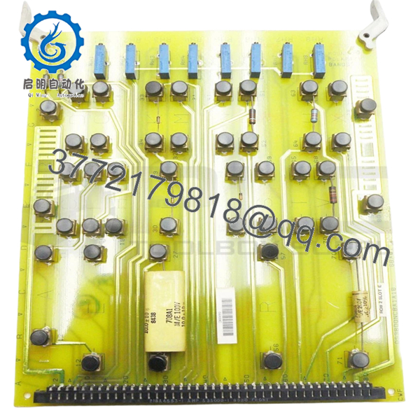
The DS3800NCBA1A1B belongs to the GE DS3800 family used in legacy turbine control environments. Available field data shows the module as a board-level assembly with multiple revision variants in circulation. Exact board functionality should be confirmed using cabinet drawings and GE Mark IV documentation before replacement.
| Parameter | Value |
|---|---|
| Manufacturer | GE |
| Model | DS3800NCBA1A1B |
| Product Family | DS3800 Series |
| System Platform | GE Mark IV Speedtronic |
| Product Type | Industrial Control PCB |
| Installation Method | Rack-mounted board |
| Hardware Revision | A1A1B |
| Communication Architecture | Proprietary GE Mark IV bus |
| Firmware Dependency | Revision sensitive |
| Service Status | Obsolete |
| Available Market Condition | New Surplus / Refurbished / Used inventory |
| Condition | New Original / New Surplus |
Inventory availability today primarily comes from surplus channels and legacy stock rather than active OEM production.
4. Product Introduction
The GE DS3800NCBA1A1B is an industrial control PCB used within GE Mark IV Speedtronic turbine control systems. It functions as a board-level assembly installed within the cabinet architecture and interfaces with the Mark IV backplane and related system electronics.
In field deployments of aging turbine controls, modules like DS3800NCBA1A1B remain in service because replacing an entire Mark IV system often means engineering redesign, recertification work, and extended shutdown windows. I have seen plants keep two or three identical spare boards on shelves because lead time uncertainty becomes a larger risk than hardware cost.

- DS3800NCBA1A1B
5. Installation & Configuration Guide
Stage 1: Pre-Installation Preparation (Estimated: 10 minutes)
⚠️ Safety First: Notify operations of downtime. Confirm equipment shutdown state. Apply lockout/tagout procedures and wait 5 minutes for capacitor discharge.
Tools Required
- ESD wrist strap
- PH1 screwdriver
- Fluke 115 multimeter
- Wire labels
- Smartphone for documentation
- ESD mat
- Flashlight
Data Backup
- Export available system settings
- Record cabinet slot position
- Photograph DIP switch positions
- Photograph cable routing
- Record connector labels
- Record board revision and assembly labels
Stage 2: Removing the Old Module (Estimated: 5–10 minutes)
Steps:
- Remove cabinet access covers
- Label every cable and connector
- Disconnect wiring carefully
- Release retention clips
- Pull board outward in a straight motion
⚠️ Note: Do not discard the original module immediately.
Inspect:
- Bent backplane pins
- Dust contamination
- Heat discoloration
- Connector wear
- Corrosion
Stage 3: Installing the New Module (Estimated: 10 minutes)
Steps:
- Attach ESD strap
- Verify exact part number: DS3800NCBA1A1B
- Configuration Clone (Crucial)
- Match DIP settings
- Match jumper positions
- Verify connector orientation
- Verify board revision labels
This is the most common rookie mistake, but it happens constantly. Take a picture before you pull it. I can’t stress this enough.
- Insert board evenly
- Confirm seating pressure
- Lock retaining hardware
- Reconnect wiring
Self-Checklist
- DIPs match
- Wiring secure
- Board seated fully
- Tabs locked
Stage 4: Power-On & Testing (Estimated: 10–15 minutes)
Pre-Power Check
Use a multimeter and verify no short exists on supply rails.
Power sequence:
- Energize rack only
- Observe startup LEDs
- Verify expected startup sequence
- Connect engineering workstation
- Confirm communication status
- Restore settings if required
- Conduct dry I/O testing
LED guidance:
- Green RUN = expected operation
- Red ERR = fault condition
⚠️ Troubleshooting Note: Immediate communication failures after replacement frequently indicate board revision differences rather than hardware failure.
I watched technicians replace three boards during a night outage. The actual problem was one revision mismatch.
Technical Pitfall & Survival Guide
❗ Firmware Revision Mismatch
Issue:
Different revisions may contain behavior changes that create communication issues.
Avoidance:
Document labels before removal and request revision matching.
I’ve seen projects spend two days troubleshooting “Communication Timeout” alarms because the replacement revision differed slightly.
❗ DIP Switch / Jumper Misconfiguration
Issue:
Default settings rarely match field requirements.
Avoidance:
Photograph everything.
This is the most common rookie mistake. It happens constantly.
❗ Terminal Block / Wiring Differences
Issue:
Connector assignments can differ between revisions.
Warning:
Even similar GE modules can change connector behavior. Always verify documentation. Never wire from memory.
❗ Power Draw Specifications
Issue:
Legacy power supplies frequently operate near capacity.
Avoidance:
Calculate total rack load and maintain a 20% power margin.
I’ve seen technicians chase phantom board failures when the cabinet power supply was already overloaded.
❗ Electrostatic Discharge (ESD)
Issue:
Board damage before startup.
Avoidance:
Use grounded ESD protection.
I once watched an engineer handle a board during winter conditions without protection. Powered once and failed immediately. Expensive lesson.
Keep these checks in mind and you’ll save yourself 90% of typical rework time.
Quality Inspection & Functional Verification SOP
1. Inbound Inspection & Traceability
- OEM packing verification
- Serial verification
- Anti-counterfeit inspection
- Visual inspection:
- corrosion
- scratches
- UV yellowing
- rework marks
- Accessory verification
2. Live Functional Testing
Test platform:
- Genuine GE Mark IV rack
- Hardware simulator
- Fluke 115 multimeter
Testing:
- Power-on diagnostics
- LED verification
- Communication handshake checks
- I/O simulation
- Continuous 24-hour load testing
- Thermal monitoring
Test reports generated.
Photos and test videos available upon request.
3. Electrical Parameter Testing
- 500 V Megger insulation test
- Greater than 10 MΩ resistance
- Ground continuity verification
- Hipot testing where applicable
4. Firmware Documentation
- Record board labels
- Photograph DIP settings
- Photograph jumper settings
5. Final QC & Packaging
- QC signoff
- Anti-static ESD packaging
- Bubble wrap protection
- Heavy-duty corrugated boxing
- QC pass labels with date
Verified fully functional under load testing.
6. Frequently Asked Questions (FAQ)
Q1: Can I hot-swap this module?
No.
GE Mark IV systems were not designed around hot-swapping. Pulling boards under power risks backplane damage and unstable communication behavior.
Power down first.
Q2: Is DS3800NCBA1A1B obsolete?
Yes.
Current inventory largely comes from surplus or refurbished channels rather than active OEM production.
Q3: Is this genuinely new?
Inventory generally falls into:
- New Original / New Surplus
- Refurbished and tested
- Used working pull inventory
Actual market inventory varies significantly.
Q4: Will I lose system programming if I remove the board?
Usually no.
Control logic often resides elsewhere within Mark IV architecture. Still, create backups before touching hardware.
Confidence disappears quickly after startup issues begin.
Q5: Why do prices vary so much?
Obsolete inventory follows availability rather than original OEM pricing.
Market listings currently range from low-cost used inventory to much higher surplus stock pricing.
Q6: Is this module tested before shipment?
Yes.
Functional testing includes startup checks, communication verification, electrical measurements, and extended load operation.
Official test reports can be supplied upon request.
Q7: Why should I verify the exact suffix A1A1B?
Suffix changes matter.
GE board suffixes frequently identify hardware revisions, assembly changes, or firmware variations. Two boards may look identical and still behave differently in a live cabinet.


