
 WhatsApp: +86 16626708626
 Email:
  Phone: +86 16626708626
Description
3. Key Technical Specifications
| Parameter | Value |
|---|---|
| Manufacturer | GE General Electric |
| Model Number | DS3800NDAC1E1F |
| Product Type | Analog Output Board |
| System Family | GE Mark IV Speedtronic |
| Primary Function | Digital-to-Analog signal output |
| Input Voltage | 24 VDC |
| Platform Integration | Mark IV Architecture |
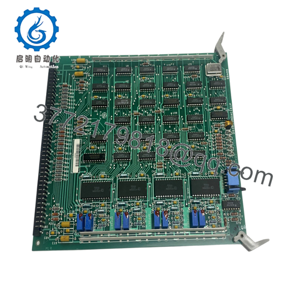
| Adjustable Components | 8 onboard potentiometers |
| Memory Components | Multiple EPROM and EEPROM devices |
| Oscillator | Single crystal oscillator |
| Indicator | Amber status LED |
| Component Count | >70 resistors and multiple diode arrays |
| Mounting Type | PCB rack installation |
| Approximate Weight | ~0.45 kg |
The DS3800NDAC1E1F is identified as a GE Mark IV Analog Output Board used for converting digital commands into analog field outputs. Hardware documentation references onboard potentiometers, EEPROM/EPROM devices, and signal conditioning components.
4. Product Introduction
GE DS3800NDAC1E1F is an Analog Output Board used within GE Mark IV Speedtronic turbine control systems. Its primary function is converting digital control signals into analog outputs used by downstream field devices and process control elements.
In field deployments of Mark IV systems, analog output boards frequently become critical spare inventory because they sit directly in the signal path. I have seen sites troubleshoot actuators, I/P converters, and field transmitters for hours before discovering an output board issue upstream. The board includes EEPROM devices, adjustable potentiometers, and dedicated signal hardware for application-specific tuning.
- DS3800NDAC1E1F
5. Installation & Configuration Guide
Stage 1: Pre-Installation Preparation
Estimated Time: 10 minutes
⚠️ Safety First: Notify operations of planned downtime. Confirm turbine process safe state. Apply lockout/tagout procedures. Wait at least 5 minutes for discharge of stored energy.
Tools Required
- ESD wrist strap
- PH1 screwdriver
- Fluke 115 multimeter
- Wire labels
- Smartphone for documentation photos
- Flashlight
Data Backup
- Record output calibration values
- Export available diagnostics
- Photograph all wiring positions
- Capture potentiometer positions
- Photograph board labels and revision markings
❗I have watched technicians replace analog cards and forget to record trim settings. Two hours later they were trying to recreate values by trial and error.
Stage 2: Removing the Old Module
Estimated Time: 5–8 minutes
- Remove panel access cover
- Label all connectors and wiring
- Disconnect cables carefully
- Release retention hardware
- Pull board straight outward
Inspect:
- Edge connector condition
- Backplane contacts
- Dust buildup
- Bent pins
- Signs of oxidation
⚠️ Keep the original board beside the rack until startup succeeds.
Old hardware becomes your troubleshooting reference.
Stage 3: Installing the New Module
Estimated Time: 5 minutes
- Wear grounded ESD protection before touching PCB
- Verify exact model: DS3800NDAC1E1F
- Configuration Clone (Crucial): Match potentiometer positions and hardware settings exactly
- Install board evenly into guide rails
- Confirm retention clips engage completely
- Reconnect field wiring
Self-Checklist
- Potentiometers documented
- Wiring secure
- Board fully seated
- Retention hardware engaged
❗This is the most common rookie mistake, but it happens constantly. Take a picture before you pull it. I can’t stress this enough.
Stage 4: Power-On & Testing
Estimated Time: 10 minutes
Pre-Power Check
Use a Fluke 115 and verify no short exists across the 24 V rail.
Power Sequence
- Energize rack only
- Observe amber LED status
- Verify communication and diagnostics
- Connect engineering workstation if available
- Simulate analog outputs before returning field devices to service
⚠️ Troubleshooting Note: If output values drift or respond incorrectly, inspect potentiometer positions before assuming board failure.
Technical Pitfall & Survival Guide
❗Firmware Revision Mismatch
Older Mark IV systems accumulated undocumented revisions over decades.
I watched one startup lose an entire shift because a replacement card behaved slightly differently than the original revision. Operators saw unstable output behavior and blamed field instrumentation.
Avoidance:
- Record revision labels before removal
- Request matching suffix revisions
- Photograph all identification tags
❗DIP Switch / Jumper Misconfiguration
The DS3800NDAC1E1F includes adjustable components and configurable hardware elements. Factory settings rarely match field installations.
Take a picture before removal.
Then take another.
❗Terminal Block / Wiring Assumptions
Even similar GE analog boards can have different signal routing.
Do not wire from memory.
Always verify drawings.
❗Power Draw Specifications
Calculate rack loading and maintain a 20% reserve.
Analog cards seem small until you stack multiple cards into aging power supplies.
❗Electrostatic Discharge
I once watched an engineer unpack a replacement board during winter without a wrist strap.
Powered once.
Never powered again.
Several thousand dollars disappeared before lunch.
Keep these checks in mind and you’ll save yourself 90% of typical rework time.
SOP Quality Transparency
1. Inbound Inspection & Traceability
- Verify OEM labels and packing records
- Review serial numbers and traceability data
- Inspect for corrosion, scratches, UV yellowing, or rework evidence
- Audit manuals and included documentation
2. Live Functional Testing
Test Environment
- Genuine GE Mark IV rack
- Simulated analog output environment
Procedure
- Power-on self-test
- LED verification
- Communication handshake checks
- Full-scale analog signal simulation
- Continuous operation >24 hr with thermal monitoring
- Formal test report generation
Test videos and photos are available upon request.
3. Electrical Parameter Testing
- 500 V Megger insulation resistance test (>10 MΩ)
- Ground continuity verification
- Hipot testing where applicable
4. Firmware & Configuration Verification
- Record hardware revision
- Photograph potentiometer positions
- Archive hardware settings
5. Final QC & Packaging
- QC inspector sign-off
- Anti-static ESD bag
- Bubble wrap protection
- Heavy-duty corrugated carton
- QC passed label with inspection date
Verified fully functional under load testing.
6. Frequently Asked Questions (FAQ)
Q1. Can I hot-swap DS3800NDAC1E1F?
No.
Do not attempt live insertion. Mark IV systems were not designed for hot-swappable analog cards. Pulling the board under power risks damaging backplane circuitry and output stages.
Power down first.
Q2. Is this model obsolete?
Yes.
GE Mark IV hardware has been discontinued for years. Existing inventory primarily comes through surplus channels and repair providers.
Q3. Is New Surplus inventory genuinely unused?
Sometimes yes.
Sometimes inventory sat untouched on a warehouse shelf for twenty years.
Request:
- Packaging photos
- Label photos
- Test reports
- Date code verification
Do not assume. Current market inventory includes NSMP and New Surplus stock listings.
Q4. What exactly does this board do?
The DS3800NDAC1E1F converts digital control signals into analog outputs for downstream process devices and control elements.
Q5. Will replacing this board erase application logic?
Typically no.
This board acts as output hardware rather than primary logic storage. Verify architecture before shutdown.
Q6. Why are market prices so different?
Obsolete turbine hardware pricing depends on condition, traceability, and testing history.
Current market examples range from approximately USD 1,100 surplus listings to over USD 4,800 for NSMP inventory with warranty support.
Q7. What should I inspect first if analog outputs behave incorrectly?
Start with:
- Potentiometer settings
- Revision matching
- Edge connector cleanliness
- Calibration values
I’ve seen output drift blamed on bad transmitters when the actual issue was a moved trim potentiometer.


