
 WhatsApp: +86 16626708626
 Email:
  Phone: +86 16626708626
Description
3. Key Technical Specifications
| Parameter | Value |
|---|---|
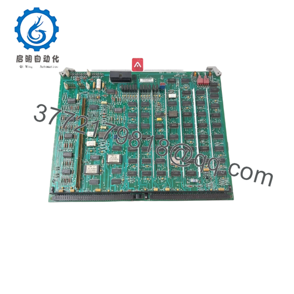
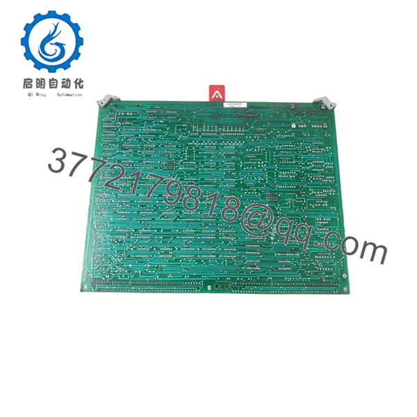
| Part Number | DS3800NFCB1U1U |
| Manufacturer | General Electric |
| Product Type | PC Board / Firing Circuit Board |
| Series | Speedtronic Mark IV DS3800 |
| Primary Function | Turbine firing circuit interface |
| System Compatibility | GE Mark IV turbine control systems |
| Mounting Style | Rack-mounted PCB |
| Connector Style | Edge connector with retention hardware |
| Application | Gas and steam turbine control cabinets |
| Operating Environment | Industrial control room / MCC enclosure |
| Cooling Method | Passive cabinet airflow |
| Approximate Weight | 900 g |
| Board Construction | Multi-layer industrial PCB |
| Condition Options | New Surplus / Refurbished Tested |
| Availability | Limited global surplus inventory |
Current surplus market references identify the DS3800NFCB1U1U as a GE firing circuit PC board used in Speedtronic Mark IV systems.
4. Product Introduction
The GE DS3800NFCB1U1U is a firing circuit PC board designed for GE Speedtronic Mark IV turbine control systems. The module operates within the DS3800 series rack architecture and supports ignition and firing-related control functions used in gas and steam turbine applications.
In field maintenance work, these boards usually appear in aging turbine installations where operators continue extending Mark IV lifecycle support instead of migrating immediately to Mark VIe platforms. Engineers typically source this board for outage spares, failed PCB replacement, or critical plant inventory stocking.

- DS3800NFCB1U1U
- DS3800NFCB1U1U
5. Installation & Configuration Guide
Stage 1: Pre-Installation Preparation (Estimated Time: 10 Minutes)
⚠️ Safety First
- Notify operations and place the turbine system into a verified shutdown condition.
- Lock out and tag out all incoming cabinet power.
- Wait at least 5 minutes for DC bus and capacitor discharge.
Tools Required
- Grounded ESD wrist strap
- PH1 screwdriver
- Fluke 115 multimeter
- Wire markers
- Smartphone for rack photos
- Inspection flashlight
Data Backup
- Export current Mark IV configuration data if engineering access is available.
- Photograph:
- Rack slot location
- Ribbon cable routing
- Jumper locations
- DIP switch positions
- Record any board revision labels and handwritten maintenance tags.
❗ I’ve seen techs swap two visually similar DS3800 boards during outage pressure. The rack powered up with multiple firing faults because the slot assignment got mixed up. Take photos before removal.
Stage 2: Removing the Old Module (Estimated Time: 5 Minutes)
- Open cabinet covers carefully.
- Label all ribbon cables and terminal connections.
- Disconnect wiring evenly without twisting the PCB.
- Release retention clips or mounting screws.
- Pull the board straight out from the rack guides.
- Inspect:
- Backplane pins
- Connector oxidation
- Dust accumulation
- Heat damage near power components
⚠️ Note: Keep the removed board available until the replacement passes operational testing.
This matters more than people realize. Older Mark IV systems often contain undocumented field modifications.
Stage 3: Installing the New Module (Estimated Time: 10 Minutes)
- Wear the grounded ESD strap before handling the replacement board.
- Verify the exact model:
- DS3800NFCB1U1U
- Inspect the PCB for:
- Broken traces
- Rework marks
- Damaged connectors
- Corrosion
- Configuration Clone (Crucial):
- Replicate all jumper settings
- Match DIP switch positions exactly
- Verify termination settings if applicable
- Insert the board carefully into rack guides.
- Press evenly until fully seated into the backplane.
- Tighten mounting hardware securely.
- Reconnect all cables using proper routing and strain relief.
Self-Checklist
- DIP switches match
- Jumpers verified
- Connectors fully seated
- Rack hardware tightened
- No loose tools inside cabinet
❗ This is the most common rookie mistake, but it still catches experienced maintenance crews during emergency outages. Photograph everything before removal.
Stage 4: Power-On & Testing (Estimated Time: 10–15 Minutes)
Pre-Power Check
- Use a multimeter to verify no short exists on the 24 V rail.
- Confirm cabinet grounding continuity.
- Verify all edge connectors are seated fully.
Power-On Steps
- Energize the control rack only.
- Observe startup LEDs and diagnostic indicators.
- Verify communication with the engineering workstation.
- Confirm the firing circuit initializes correctly.
- Check rack diagnostics for communication or watchdog faults.
- Perform dry-run verification before enabling field outputs.
⚠️ Troubleshooting Note
- Solid fault LEDs usually indicate configuration mismatch or failed initialization.
- Communication failures commonly trace back to:
- Misaligned edge connectors
- Incorrect jumper settings
- Bent backplane pins
I’ve personally watched a startup delayed nearly 12 hours because a replacement board shipped with different jumper defaults than the original site hardware.
6. Frequently Asked Questions (FAQ)
Q1: Can I hot-swap the DS3800NFCB1U1U while the rack is energized?
No. Do not hot-swap this module.
The Mark IV platform was not designed for online board replacement. Pulling the board under power risks damaging the backplane or corrupting firing control signals. Shut the cabinet down fully before removal.
Q2: Is the DS3800NFCB1U1U still manufactured by GE?
No. This module is obsolete.
Current inventory normally comes from:
- New surplus stock
- Decommissioned plant inventory
- Refurbished and tested boards
Supply is limited because many power plants still maintain Mark IV systems for lifecycle extension projects.
Q3: What does this board actually do inside the Mark IV system?
The DS3800NFCB1U1U functions as a firing circuit PC board associated with turbine ignition and firing control operations within the Speedtronic architecture. Exact behavior depends on rack configuration and turbine application.
Always verify against the original GE prints and cabinet drawings before replacement. Mark IV configurations varied significantly between sites.
Q4: Will I lose turbine logic or configuration when replacing this board?
Normally the primary application logic remains stored elsewhere in the Mark IV control architecture.
Still, never assume memory retention. Before shutdown:
- Back up available configuration files
- Photograph switch settings
- Record firmware revisions
I’ve seen maintenance teams replace a board successfully, only to discover later that undocumented jumper settings changed startup timing behavior.
Q5: Why do some suppliers list this board as “new surplus” instead of new OEM?
Because GE no longer manufactures these boards through normal production channels.
“New surplus” usually means:
- Never installed
- Stored inventory
- Open-box industrial stock
- Legacy warehouse inventory
Ask for:
- Actual board photos
- Date codes
- Inspection reports
- Power-on test evidence
If the seller only provides stock photos, proceed carefully.
Q6: What should I inspect before installing a replacement board?
Minimum inspection should include:
- Connector pin condition
- PCB trace integrity
- Capacitor leakage
- Jumper positions
- Corrosion around edge connectors
- Firmware or revision labels
Even boards with identical base numbers can behave differently across revision levels.
Q7: What testing should a supplier perform before shipment?
At minimum:
- Visual inspection under magnification
- 500 V insulation resistance test (>10 MΩ)
- Ground continuity verification
- Rack communication testing
- 24-hour powered burn-in test
- ESD-safe packaging with anti-static sealing
Good suppliers normally provide:
- Startup photos
- Test reports
- Rack test videos
- Revision verification documentation
Test videos and photos should be available upon request. Keep these checks in mind and you’ll avoid most field replacement headaches.


