
 WhatsApp: +86 16626708626
 Email:
  Phone: +86 16626708626
Description
3. Key Technical Specifications
| Parameter | Value / Specification |
| Manufacturer | General Electric (GE) |
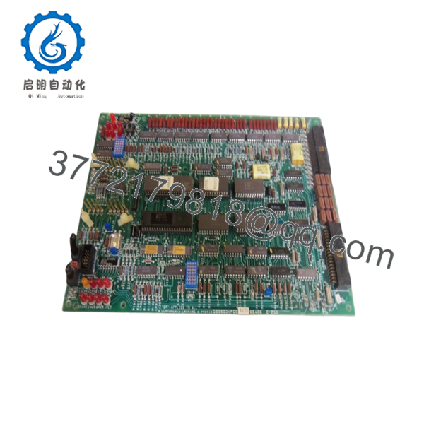
| Part Number | DS3800NFCD1K1D |
| System Compatibility | Mark IV Speedtronic Turbine Control / Power Inverter Drive |
| Application | SCR Firing / Gate Pulse Generation |
| Circuit Type | High-speed pulse transformer coupled output |
| Revision Level | D1K1D (Specific factory firmware and component configuration) |
| Connectors | Multi-pin edge backplane connector and onboard test points |
| Indicators | Diagnostic LEDs for power and pulse activity verification |
| Operating Temperature | 0 to +60°C |
| Storage Temperature | −40 to +85°C |
4. Product Introduction & Supply Chain Strategy
The GE DS3800NFCD1K1D functions as a dedicated firing circuit board within legacy GE Mark IV Speedtronic turbine controllers and associated static power conversion systems. Its primary technical operation involves generating high-precision, synchronized gating pulses sent to heavy-duty Silicon Controlled Rectifiers (SCRs) to manage electrical rectifying and inversion cycles. By regulating SCR conduction angles, this board coordinates the stable flow of raw excitation and auxiliary power to major generator subsystems during active run sequences.
Securing a verified New Surplus unit for this specific part number is an essential supply chain strategy for capital asset protection. Because the original equipment manufacturer ceased technical production for this line decades ago, single-point module failures present an immediate threat of extended, unresolvable plant downtime. Procuring factory-sealed inventory eliminates the high failure rates and component degradation risks associated with refurbished or repaired cards. This direct strategy actively reduces your aggregate Total Cost of Ownership (TCO) by providing drop-in reliability that matches the original plant commissioning standards.

- DS3800NFCD1K1D
5. Installation & Configuration Guide
Stage 1: Pre-Installation (Prep & Safety)
- Enforce strict lock-out/tag-out (LOTO) procedures on all three-phase AC input lines and auxiliary DC control buses supplying the target inverter cube or turbine rack.
- Allow a minimum of 10 minutes for any high-voltage DC bus filter capacitors to fully discharge through their bleeder resistors, then verify a zero-energy state with a calibrated multimeter.
- Fasten a grounded anti-static wrist strap to your wrist and attach the clip to a verified ground lug on the equipment frame.
- Photograph all onboard jumper arrangements, trace wire routings, and structural DIP switch selections to preserve custom calibration parameters.
Stage 2: Removal
- Carefully label and unseat front-facing high-frequency pulse transformer wires or ribbon cables connected directly to the board face.
- Disengage the locking ears or mechanical retaining hardware anchoring the card to the sub-rack housing.
- Simultaneously press the top and bottom extraction tabs outward to unseat the module from its backplane socket, drawing the card toward you along the guide channels horizontally to protect vulnerable pin headers.
Stage 3: Installation (Clone & Seat)
- Remove the new surplus DS3800NFCD1K1D board from its sealed static-shielding bag inside an ESD-protected zone.
- Set every jumper and DIP switch array on the new surplus card to replicate the old module exactly.
- Position the board within the correct guide slots and glide it smoothly into the rack until the rear connectors touch the backplane alignment point. Press firmly until the mechanical extraction ears snap inward, confirming a secure, zero-gap seat.
Stage 4: Power-On & Testing
- Reattach all external gate leads and ribbon connectors to their corresponding terminals.
- Energize the low-voltage auxiliary DC control rails first, keeping a safe distance while monitoring local Diagnostic LEDs for steady illumination.
- Check for the absence of localized logic faults, cross-talk anomalies, or gate-drive error indicators before re-introducing heavy-duty primary power to the SCR bridge.
6. Firmware/Software Versions & Upgrade Notes
The hardware configuration on the DS3800NFCD1K1D is defined by the complex suffix revision identifier “D1K1D”. This designation denotes the exact bill of materials, circuit timing capacitors, and pulse-forming networks installed on the board at manufacture.
⚠️ CRITICAL WARNING: Suffix revisions for firing circuit modules are highly sensitive. Mixing a “D1K1D” layout with an older version card (such as a baseline “D1D” or “C1B”) inside a shared redundant gating network can cause microsecond propagation delays in pulse execution. This variation leads to asymmetric SCR conduction, creating balanced load anomalies, harmonic saturation in the transformer windings, or total bridge destruction. Match the entire code configuration across all active phases.
7. Frequently Asked Questions (FAQ)
- Why choose a New Surplus unit over a less expensive refurbished DS3800NFCD1K1D board?
Refurbished gate-firing modules carry significant hidden risks because they use older capacitors and pulse transformers exposed to thousands of hours of intense thermal cycles. Sourcing a New Surplus unit provides a completely unaged, pristine board layout with fresh components, effectively shielding your operations from the steep collateral costs of a sudden gate-driver failure.
- Is special programming or software loading needed for this card?
No software loading or field programming is required. The board uses dedicated analog and discrete digital logic structures. All custom operational profiles are handled entirely via physical hardware jumpers and on-board DIP switches, allowing immediate plug-and-play installation when cloned properly.
- What functions do the high-frequency pulse transformers serve on this board?
The pulse transformers provide electrical isolation between the low-voltage control microprocessors and the high-voltage, high-current environments of the main SCR power bridge. This keeps dangerous voltage spikes from flowing back into your sensitive automation system backplane.
- Can I perform a hot-swap with this firing circuit board while the drive system is active?
Absolutely not. Pulling a firing board while energized leaves the gating inputs floating, which can randomly trigger high-power SCR elements simultaneously. This mistake results in direct phase-to-phase short circuits that destroy expensive power hardware. Always completely de-energize the entire cabinet before servicing.
- Does this unit come with a formal product warranty?
Yes, this New Surplus component is covered by a 1-year warranty starting on your purchase date, offering long-term investment protection equivalent to an original OEM item.


