
 WhatsApp: +86 16626708626
 Email:
  Phone: +86 16626708626
Description
3. Key Technical Specifications
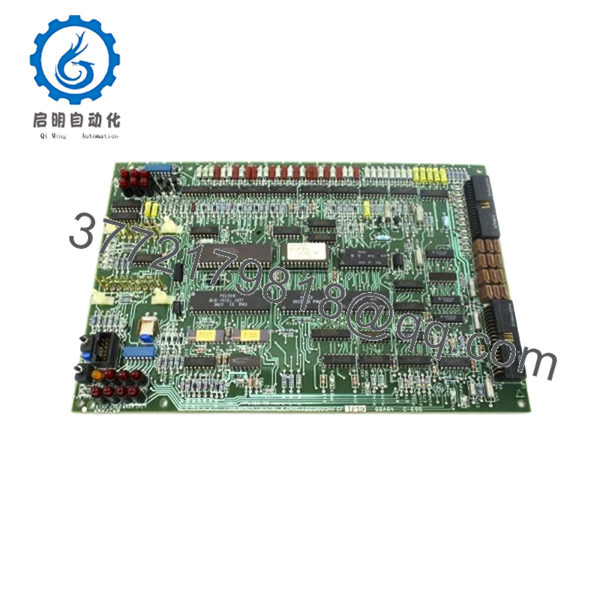
The GE DS3800NFCF1F1D is identified as a Mark IV firing circuit board used in GE Speedtronic turbine systems. Field documentation indicates the board contains onboard diagnostics, jumper configuration capability, and support circuitry for signal handling and firing operations.
| Parameter | Value |
|---|---|
| Manufacturer | GE |
| Model | DS3800NFCF1F1D |
| System Platform | GE Mark IV Speedtronic |
| Product Type | Firing Circuit Board |
| Board Group | Group 1 |
| Board Revision | F1F1D |
| MOS RAM | 8-bit static RAM |
| RAM Organization | 256 × 8 cells |
| Access Time | 400 ns |
| LED Indicators | 15 onboard LEDs |
| Test Points | 29 |
| Transistors | 21 |
| Jumpers | 2 |
| Crystal Oscillators | 11.000 MHz |
| Connector Count | 3 |
| Condition | New Original / New Surplus |
The board can interface with an auxiliary DS3800DFCF assembly through board-to-board connections and physical support pins.
4. Product Introduction
The GE DS3800NFCF1F1D is a firing circuit board designed for the GE Mark IV Speedtronic turbine control platform. It participates in signal handling and firing control functions used within gas and steam turbine systems and operates through the Mark IV control architecture.
In field deployments of older turbine systems, firing boards are not modules I swap casually during a shutdown. A revision mismatch in a board like this can consume more outage time than the actual hardware replacement. Plants often keep identical spare revisions on shelves because lead times for obsolete assemblies can become unpredictable.

- DS3800NFCF1F1D
- DS3800NFCF1F1D
5. Installation & Configuration Guide
Stage 1: Pre-Installation Preparation (Estimated: 10 minutes)
⚠️ Safety First: Notify operations of planned downtime. Verify equipment is in a safe state. Apply lockout/tagout procedures and wait 5 minutes after power removal.
Tools Required
- ESD wrist strap
- PH1 screwdriver
- Fluke 115 multimeter
- Wire labels
- Smartphone for photos
- ESD mat
- Flashlight
Data Backup
- Export controller settings where available
- Record cabinet slot position
- Photograph jumper and DIP settings
- Record connector orientation
- Photograph cable routing
- Record revision labels
Stage 2: Removing the Old Module (Estimated: 5–10 minutes)
Steps:
- Remove cabinet covers
- Label all wiring and connectors
- Disconnect cables carefully
- Release retaining hardware
- Pull board outward evenly
⚠️ Note: Keep the removed board nearby until successful startup verification.
Inspect:
- Bent backplane pins
- Dust contamination
- Connector wear
- Corrosion
- Heat damage
Stage 3: Installing the New Module (Estimated: 10 minutes)
Steps:
- Connect ESD strap
- Verify DS3800NFCF1F1D exactly matches
- Configuration Clone (Crucial):
- Match jumper settings
- Match switch positions
- Verify board revision
- Verify connector orientation
This is the most common rookie mistake, but it happens constantly. Take a picture before you pull it. I can’t stress this enough.
- Insert board into guide rails
- Confirm full seating
- Lock retention hardware
- Reconnect all cables
Self-Checklist
- DIPs match
- Jumpers match
- Wiring secure
- Board fully seated
Stage 4: Power-On & Testing (Estimated: 10–15 minutes)
Pre-Power Check
Use a multimeter and verify no short exists on cabinet power rails.
Power sequence:
- Power rack only
- Observe startup LEDs
- Verify expected LED sequence
- Connect engineering workstation
- Verify communication state
- Restore backups if needed
- Run dry I/O verification
LED guidance:
- Green RUN = expected operation
- Red ERR = fault condition
⚠️ Troubleshooting Note: A solid fault indication after replacement frequently points toward board revision mismatch.
I have seen maintenance crews replace multiple boards before discovering the replacement revision shifted communication behavior.
Technical Pitfall & Survival Guide
❗ Firmware Revision Mismatch
Issue:
Replacement revisions can behave differently from the original board.
Avoidance:
Record firmware and board labels before removal.
I’ve seen outages stretch for two days because a board moved from one revision family to another and generated communication alarms.
❗ DIP Switch / Jumper Misconfiguration
Issue:
Factory settings rarely match field settings.
Avoidance:
Photograph everything before removal.
This is the most common rookie mistake. It happens constantly.
❗ Terminal Block / Wiring Incompatibility
Issue:
Connector assignments may differ between revisions.
Warning:
Even similar GE DS3800 boards occasionally shift signal definitions. Verify manuals. Never wire from memory.
❗ Power Draw Specifications
Issue:
Legacy cabinet supplies frequently run near capacity.
Avoidance:
Calculate total rack loading and leave a 20% reserve.
A replacement board sometimes gets blamed for faults actually caused by overloaded supplies.
❗ Electrostatic Discharge (ESD)
Issue:
Board damage before startup.
Avoidance:
Wear grounded protection and use an ESD surface.
I once watched an engineer handle a board in dry winter conditions without protection. Powered once and failed immediately.
Keep these checks in mind and you’ll save yourself 90% of typical rework time.
Quality Inspection & Functional Verification SOP
1. Inbound Inspection & Traceability
- OEM packing verification
- Serial number validation
- Anti-counterfeit inspection
- Visual inspection:
- scratches
- corrosion
- UV discoloration
- rework marks
- Accessory audit
2. Live Functional Testing
Test environment:
- Genuine GE Mark IV rack
- Simulated cabinet setup
- Fluke 115 multimeter
Testing:
- Power-on diagnostics
- LED verification
- Communication handshake checks
- I/O simulation
- Continuous 24-hour load operation
- Thermal monitoring
Official test reports generated.
Test photos and videos available upon request.
3. Electrical Parameter Testing
- Insulation resistance:
- 500 V Megger
- Greater than 10 MΩ
- Ground continuity checks
- Hipot testing where applicable
4. Firmware Documentation
- Record revision identifiers
- Photograph jumper positions
- Photograph switch settings
5. Final QC & Packaging
- QC signoff
- Anti-static ESD packaging
- Bubble wrap protection
- Heavy-duty corrugated box
- QC labels with date
Verified fully functional under load testing.
6. Frequently Asked Questions (FAQ)
Q1: Can I hot-swap this module?
No.
GE Mark IV hardware was not designed for live board replacement. Pulling boards under power risks backplane damage and unstable communication behavior.
Q2: Is DS3800NFCF1F1D obsolete?
Yes.
The board belongs to a discontinued Mark IV platform and inventory generally comes from surplus stock or tested legacy inventories.
Q3: Is this genuinely new?
Available inventory typically falls into:
- New Original / New Surplus
- Refurbished and tested
- Used pull inventory
Always request actual inventory photos.
Q4: What does this board actually do?
It functions as a firing circuit board within the Mark IV turbine control architecture and contains processing and signal circuitry used in firing operations.
Q5: Will I lose programming if I remove the board?
Usually no.
Control logic generally resides elsewhere in the Mark IV architecture. Still, never assume. Create backups before touching hardware.
Q6: Why do obsolete board prices vary so much?
Supply drives pricing.
These assemblies often come from shutdown inventories, canceled projects, and spare stock liquidations.
Q7: Is this module tested before shipment?
Yes.
Testing includes startup diagnostics, communication verification, electrical testing, and extended load operation testing before QC approval.


