
 WhatsApp: +86 16626708626
 Email:
  Phone: +86 16626708626
Description
3. Key Technical Specifications
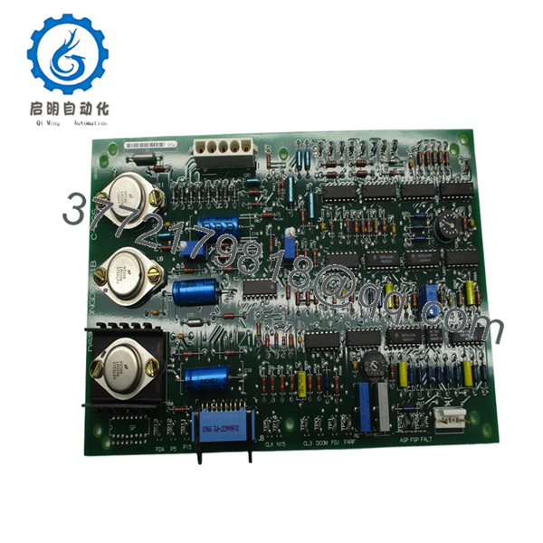
The GE DS3800NGDD is identified as a Field Ground Detector card used within GE Mark IV Speedtronic turbine systems. Its primary purpose is monitoring field circuits for ground-fault conditions and reporting abnormalities before they escalate into larger system failures. Legacy inventory often appears under suffix variants such as DS3800NGDD1C1B, so exact revision matching matters.
| Parameter | Value |
|---|---|
| Manufacturer | GE |
| Model | DS3800NGDD |
| System Platform | GE Mark IV Speedtronic |
| Product Type | Field Ground Detector Card |
| Primary Function | Field grounding fault detection |
| Installation Type | Rack-mounted PCB assembly |
| Communication Architecture | Proprietary Mark IV bus |
| Revision Sensitivity | High |
| Typical Application | Gas and steam turbine controls |
| Product Lifecycle | Obsolete |
| Market Availability | Surplus / Refurbished / Open Box |
| Condition | New Original / New Surplus |
Field inventories also show DS3800NGDD modules offered in New Surplus and tested conditions with active stock in secondary supply channels.
4. Product Introduction
The GE DS3800NGDD is a Field Ground Detector card designed for GE Mark IV Speedtronic turbine control systems. The board continuously monitors field circuits and detects grounding abnormalities that can create unstable operation or larger electrical failures.
In field deployments of older turbine systems, ground detector boards quietly become critical hardware. Nobody notices them until a nuisance trip or intermittent fault starts showing up at 2:00 AM. I have seen plants replace power supplies and I/O boards before discovering the actual issue was a deteriorating ground path detected by the original DS3800NGDD. Proper diagnostics save outage hours.

- DS3800NGDD
- DS3800NGDD
5. Installation & Configuration Guide
Stage 1: Pre-Installation Preparation (Estimated: 10 minutes)
⚠️ Safety First: Notify operations personnel of planned downtime. Verify process shutdown. Apply lockout/tagout procedures and wait 5 minutes after power removal.
Tools Required
- ESD wrist strap
- PH1 screwdriver
- Fluke 115 multimeter
- Wire labels
- Smartphone for photos
- ESD work mat
- Flashlight
Data Backup
- Export system settings where possible
- Record cabinet location and slot position
- Photograph all DIP switches and jumper settings
- Photograph wiring layout
- Record board revision labels
- Document connector locations
Stage 2: Removing the Old Module (Estimated: 5–10 minutes)
Steps:
- Remove cabinet access panels
- Label all connectors
- Disconnect cables carefully
- Release retention hardware
- Pull board straight outward
⚠️ Note: Keep the old board nearby until startup completes successfully.
Inspect:
- Bent backplane pins
- Dust contamination
- Corrosion
- Connector wear
- Heat discoloration
Stage 3: Installing the New Module (Estimated: 10 minutes)
Steps:
- Connect ESD strap
- Verify exact part number: DS3800NGDD
- Configuration Clone (Crucial):
- Match DIP settings
- Match jumper positions
- Match revision labels
- Verify connector orientation
This is the most common rookie mistake, but it happens constantly. Take a picture before you pull it. I can’t stress this enough.
- Insert board evenly
- Confirm full seating
- Secure locking hardware
- Reconnect wiring
Self-Checklist
- DIPs match
- Jumpers match
- Wiring secure
- Board seated fully
Stage 4: Power-On & Testing (Estimated: 10–15 minutes)
Pre-Power Check
Use a multimeter and verify no short exists on power rails.
Power sequence:
- Energize rack only
- Observe LED behavior
- Verify startup sequence
- Connect engineering workstation
- Verify communication status
- Restore configuration if required
- Conduct dry-run testing
LED guidance:
- Green RUN = expected operation
- Red ERR = fault condition
⚠️ Troubleshooting Note: If the board powers correctly but intermittent alarms continue, inspect field grounding before replacing additional hardware.
I’ve watched maintenance teams swap multiple boards during overnight outages when the actual issue was shielding bonded incorrectly at both ends.
Technical Pitfall & Survival Guide
❗ Firmware Revision Mismatch
Issue:
Replacement boards with different revisions occasionally alter communication timing.
Avoidance:
Document firmware labels before removal.
I’ve seen projects lose two days chasing “Communication Timeout” alarms because firmware changed between revisions.
❗ DIP Switch / Jumper Misconfiguration
Issue:
Factory defaults rarely match plant settings.
Avoidance:
Photograph every switch before removal.
This is the most common rookie mistake. It happens constantly.
❗ Terminal Block / Wiring Differences
Issue:
Connector assignments occasionally change between revisions.
Warning:
Even similar GE DS3800 boards can differ. Verify documentation. Never wire from memory.
❗ Power Draw Specifications
Issue:
Legacy cabinets often operate close to power supply limits.
Avoidance:
Calculate rack loading and maintain a 20% capacity margin.
For reference, overloaded cabinet supplies frequently create startup behavior that looks like communication failure.
❗ Electrostatic Discharge (ESD)
Issue:
Board damage before installation.
Avoidance:
Use grounded wrist straps and ESD mats.
I once watched a technician unpack a board in dry winter conditions without protection. It powered once and failed immediately. Expensive lesson.
Keep these checks in mind and you’ll save yourself 90% of typical rework time.
Quality Inspection & Functional Verification SOP
1. Inbound Inspection & Traceability
- OEM packing verification
- Serial number validation
- Anti-counterfeit inspection
- Visual inspection:
- corrosion
- scratches
- UV yellowing
- rework marks
- Accessory verification
2. Live Functional Testing
Test environment:
- Genuine GE Mark IV rack
- Simulation environment
- Fluke 115 multimeter
Testing:
- Power-on diagnostics
- LED startup checks
- Communication handshake testing
- Signal simulation
- Continuous 24-hour load operation
- Thermal monitoring
Official test reports generated.
Test videos and photos available upon request.
3. Electrical Parameter Testing
- 500 V Megger insulation test
- Greater than 10 MΩ insulation resistance
- Ground continuity verification
- Hipot testing where applicable
4. Firmware Documentation
- Record firmware identifiers
- Photograph switch positions
- Photograph jumper locations
5. Final QC & Packaging
- QC sign-off
- Anti-static ESD packaging
- Bubble protection
- Heavy-duty corrugated packaging
- QC labels with inspection date
Verified fully functional under load testing.
6. Frequently Asked Questions (FAQ)
Q1: Can I hot-swap this module?
No.
GE Mark IV architecture was not designed around hot-swappable field hardware. Pulling the module under power risks backplane faults and communication instability.
Power down first.
Q2: Is DS3800NGDD obsolete?
Yes.
The module belongs to the discontinued Mark IV platform and is primarily available through surplus inventory channels today.
Q3: Is this genuinely new?
Current market inventory usually includes:
- New Original / New Surplus
- Refurbished and tested
- Open-box surplus inventory
Several suppliers list active New Surplus stock with warranty coverage.
Q4: What exactly does this board do?
The board continuously monitors field circuits for grounding faults and reports abnormalities before they escalate into larger electrical problems.
Q5: Will I lose control programming if I remove the board?
Usually no.
Control logic normally resides elsewhere in Mark IV architecture, but never assume. Create backups before touching hardware.
Q6: Why do prices vary so much?
Obsolete hardware pricing follows availability rather than original list price.
These boards often come from shutdown inventory, spare stock liquidation, and project cancellations.
Q7: Is the board tested before shipment?
Yes.
Testing includes startup diagnostics, communication checks, insulation measurements, and extended operational load testing before QC release.


