
 WhatsApp: +86 16626708626
 Email:
  Phone: +86 16626708626
Description
3. Key Technical Specifications
| Parameter | Value |
|---|---|
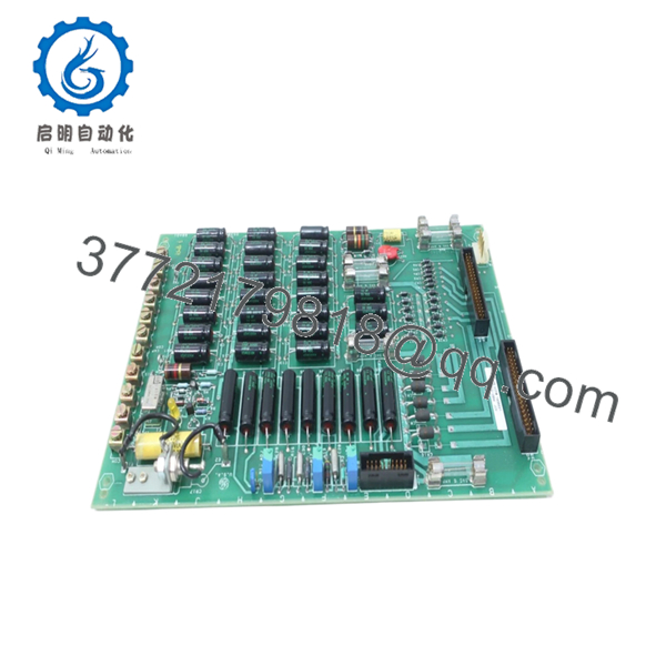
| Model Number | DS3800NPSE1A1A |
| Manufacturer | General Electric |
| Product Category | Power Supply Circuit Board |
| System Series | Speedtronic Mark IV DS3800 |
| Application | Gas and steam turbine control systems |
| Installation Type | Rack-mounted PCB assembly |
| Connector Interfaces | Three onboard connection ports |
| Adjustable Components | Three onboard potentiometers |
| Protective Components | MOV surge protection element |
| Operating Environment | Industrial control cabinet |
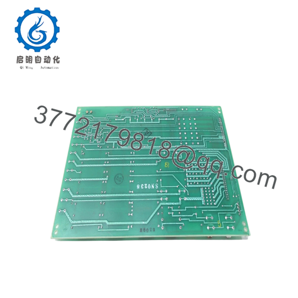
| PCB Construction | Multi-component discrete board |
| Product Status | Obsolete / Surplus inventory market |
| Condition Options | New Surplus / Refurbished (tested) |
Several hardware details come directly from field inventory documentation and board inspection records.
4. Product Introduction
GE DS3800NPSE1A1A is a power supply circuit board used in the GE Speedtronic Mark IV turbine control platform. It regulates and distributes power for control circuitry in gas and steam turbine applications where stable operation of control hardware is critical.
In field deployments of Mark IV systems, these boards usually appear in legacy turbine cabinets still running for decades beyond their original lifecycle. Plants often keep replacement inventory because an unexpected board failure can stop an entire turbine train. Availability matters more than cosmetic condition in these cases. Verify exact suffix revisions before installation.

- DS3800NPSE1A1A
- DS3800NPSE1A1A
5. Installation & Configuration Guide
Stage 1: Pre-Installation Preparation (Estimated: 10 minutes)
⚠️ Safety First: Notify operations of downtime. Verify the turbine is in a safe shutdown state. Apply lockout/tagout procedures and remove control power. Wait at least 5 minutes for capacitor discharge.
Tools Required:
- ESD wrist strap
- PH1 screwdriver
- Fluke 115 multimeter
- Wire labels
- Smartphone for documentation
- ESD work surface
Data Backup:
- Export existing controller configuration if applicable.
- Record cabinet power measurements.
- Photograph terminal wiring.
- Photograph connector orientation.
- Photograph any jumpers or board settings.
Stage 2: Removing the Old Module (Estimated: 5 minutes)
- Remove cabinet access panels.
- Label and disconnect wiring carefully.
- Release mounting hardware and board retention tabs.
- Pull the board straight outward. Do not rock side to side.
- Inspect mating connectors and backplane contacts.
⚠️ Note: Keep the old board nearby until the replacement runs correctly.
I’ve seen technicians toss failed boards into scrap bins immediately. Two hours later they realize they forgot to document connector orientation.
Stage 3: Installing the New Module (Estimated: 10 minutes)
- Connect ESD protection before touching the board.
- Verify exact model number: DS3800NPSE1A1A
- Configuration Clone (Crucial): Match all jumper positions and connector arrangements exactly.
- Insert the board straight into position.
- Confirm complete seating and retention engagement.
- Reconnect wiring using proper torque practices.
Self-Checklist:
- Board revision verified
- Wiring secure
- Connectors fully seated
- Retention tabs locked
- ESD handling used
⚠️ This is the most common rookie mistake, but it happens constantly. Take a picture before you pull it. I can’t stress this enough.
Stage 4: Power-On & Testing (Estimated: 10 minutes)
Pre-Power Check
Use a Fluke meter to verify no short exists across the 24 V rail.
Power-On sequence:
- Power the rack only.
- Observe startup indicators.
- Verify communication and power stability.
- Restore configuration if required.
- Perform dry-run signal testing.
⚠️ Troubleshooting Note: If communication faults appear immediately, suspect revision mismatch before assuming board failure.
I’ve seen projects lose two days because a replacement board revision behaved differently than expected.
Technical Pitfall & Survival Guide
❗ Firmware Revision Mismatch
Issue: Older Mark IV systems occasionally react badly to hardware revisions.
Avoidance: Record every revision number before pulling the old board.
I’ve watched maintenance teams chase a “Communication Timeout” alarm for two days because one replacement carried a newer board revision.
❗ DIP Switch / Jumper Misconfiguration
Issue: Factory defaults rarely match plant configurations.
Avoidance: Photograph everything before removal.
This mistake appears constantly during midnight outages.
❗ Terminal Block Compatibility
Issue: Connector and pin arrangements sometimes vary across suffix revisions.
Avoidance: Verify documentation and compare physically.
Even boards that look identical can route signals differently.
❗ Power Draw Calculations
Issue: Extra load can push cabinet supplies beyond margin.
Avoidance: Keep approximately 20% power headroom.
A loaded turbine cabinet can surprise you quickly.
❗ Electrostatic Discharge (ESD)
Issue: Static damage occurs before installation.
Avoidance: Use grounded wrist straps and ESD mats.
I once watched an engineer handle a board during winter without protection. Power came on and smoke followed immediately. Expensive lesson.
Keep these checks in mind and you’ll save yourself 90% of typical rework time.
6. Frequently Asked Questions (FAQ)
Q1: Can I hot-swap this module?
No. Kill power first.
Mark IV hardware was not designed around modern hot-swap concepts. Pulling boards live can damage connectors, create transient faults, or affect adjacent circuitry.
Q2: Is GE DS3800NPSE1A1A obsolete?
Yes.
The Speedtronic Mark IV platform is a legacy GE system. Most inventory today comes from surplus channels or refurbished stock.
Q3: Is this genuinely new?
Usually “New Original” means unused surplus inventory from industrial stockrooms. Factory packaging may or may not remain intact after decades of storage.
Ask for board photos and serial verification.
Q4: What happens to my program when I remove the board?
This board is a power supply assembly rather than a controller CPU.
The control logic generally resides elsewhere in the Mark IV system. Still, document system settings before shutdown.
Q5: Why are some prices much lower than GE historical pricing?
Because OEM production ended years ago.
Current pricing depends on surplus inventory, condition, testing history, and urgency. Supply can change week to week.
Q6: Do you test surplus inventory before shipment?
Yes. Our SOP process follows a documented sequence:
- OEM source and serial verification
- Anti-counterfeit inspection
- Visual inspection for corrosion and rework marks
- Power-on verification on genuine test hardware where available
- Communication checks
- Insulation testing using 500 V Megger (>10 MΩ)
- Firmware and hardware documentation
- QC signoff with ESD packaging
Test videos and photos are available upon request.
Q7: What if the board powers up but the system still faults?
Start with revision checks and wiring verification.
At 2 AM during outages, people immediately blame the replacement part. Half the time the issue is a missed connector, an undocumented jumper, or a configuration mismatch. Debug methodically.


