
 WhatsApp: +86 16626708626
 Email:
  Phone: +86 16626708626
Description
Key Technical Specifications
| Parameter | Value |
| System Compatibility | GE Mark IV Speedtronic Turbine Control |
| Output Type | Electromechanical Relay Contacts |
| Contact Rating | Typically 125 V DC / 250 V AC (Application dependent) |
| Interface | Standard GE DS3800 Edge Connector |
| Input Logic | TTL/CMOS Compatible levels from Master Controller |
| Mounting | Card Cage / Rack Mount |
| Revision | 1D1C (Specific revision for hardware/software parity) |
| Isolation | Galvanic isolation between control logic and field circuits |
Product Introduction & Supply Chain Strategy
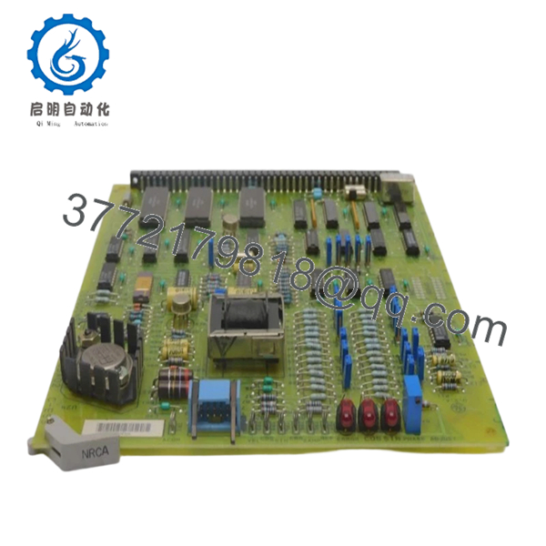
The GE DS3800NRCA1D1C is a fundamental relay output termination board within the Mark IV Speedtronic control system. This module serves as the physical bridge between low-level microprocessor logic and high-power field devices, such as solenoid valves, motor starters, and auxiliary pumps. By providing essential electrical isolation and signal switching, the NRCA board ensures that the sensitive digital core of the turbine controller remains protected from field-side electrical noise and surges.
Strategically, the DS3800NRCA1D1C is a high-impact component for risk management. Because relay contacts have a finite mechanical lifespan and are susceptible to contact pitting over decades of operation, these boards are frequent failure points in legacy installations. Sourcing “New Surplus” units is the most effective way to lower the Total Cost of Ownership (TCO); it avoids the unpredictable failure rates of refurbished boards that may have weakened solder joints or degraded relay coils. Keeping a verified New Surplus spare on-site is an essential “insurance policy” to prevent millions of dollars in lost production due to a simple contact failure.

- DS3800NRCA1D1C
- DS3800NRCA1D1C
Installation & Configuration Guide
Stage 1: Pre-Installation (Prep & Safety)
- Lock-out/Tag-out: Fully de-energize the turbine control rack and the associated field power supplies.
- Jumper Verification: Examine the jumpers (e.g., JP1, JP2) on your existing board. These often define relay logic (Normally Open vs. Normally Closed). Set the new NRCA1D1C to match perfectly.
- ESD Protocol: Use a grounded wrist strap. The logic interface chips on this board are sensitive to electrostatic discharge.
Stage 2: Removal
- Open the card cage door and locate the faulty board.
- Gently pull the card ejector tabs outward. Slide the board out of the guide rails, ensuring it does not snag on adjacent wiring.
Stage 3: Installation (Clone & Seat)
- Align the DS3800NRCA1D1C with the guide rails.
- Firmly push the board until the edge connector is fully seated in the backplane. You should feel a distinct “click” as it engages.
Stage 4: Power-On & Testing
- Re-apply power to the control system.
- Monitor the system diagnostics for any “Board Mismatch” or “I/O Fault” codes.
- Perform a functional test by forcing the associated outputs via the Mark IV operator interface to ensure the relays click and the field devices actuate.
Firmware/Software Versions & Upgrade Notes
- Revision Parity: The “1D1C” suffix indicates a specific revision level. While some GE boards are backward compatible, ensure your system software recognizes this revision level to avoid communication errors or diagnostic flags.
- No Local Firmware: This board acts primarily as a hardware interface; there is no onboard firmware to flash. However, the system-level I/O configuration in the Master Controller must match the board’s physical slot and jumper settings.
- Redundancy Note: In TMR (Triple Modular Redundant) systems, if replacing an NRCA board in one core (<R>, <S>, or <T>), ensure the logic remains synchronized across all three to prevent voting mismatches.
Frequently Asked Questions (FAQ)
Is this board used or pulled from a working system?
No. This is a New Surplus unit. It has never been installed in a field environment. Unlike “refurbished” boards that are often cleaned and resold, our units provide the reliability of original factory-new hardware.
What is the most common cause of failure for the NRCA board?
The most common failures are mechanical wear of the relay contacts or coil burnout due to prolonged use in high-heat environments. Since our units are New Surplus, they feature zero-hour relays with full mechanical life expectancy.
Can I use this in a Mark V system?
No. The DS3800 series is specifically designed for the Mark IV card cage architecture. Mark V systems use the DS200 or DS215 series boards, which have different form factors and electrical interfaces.
How do I know if my jumpers are set correctly?
Always refer to the wiring diagram specific to your turbine. If those are unavailable, the safest method is a 1-to-1 physical clone of the jumpers from the board you are replacing.
Does this board come with a warranty?
Yes, we provide a warranty on all New Surplus GE Mark IV components. We ensure that every board is stored in an ESD-safe, climate-controlled environment to prevent component aging.


