
 WhatsApp: +86 16626708626
 Email:
  Phone: +86 16626708626
Description
3. Key Technical Specifications
| Parameter | Value |
|---|---|
| Manufacturer | GE General Electric |
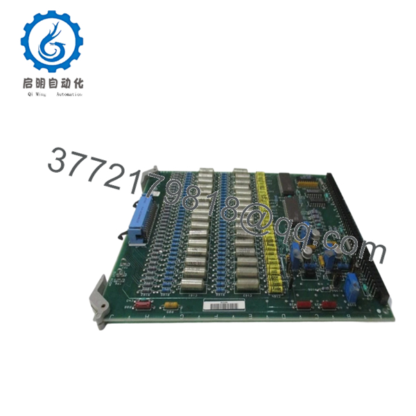
| Model Number | DS3800NTCF1A1A |
| Product Type | Turbine Control Board |
| System Family | GE Speedtronic Mark IV |
| Platform | DS3800 Series |
| Application | Gas and steam turbine control |
| Installation Type | Rack-mounted PCB |
| Functional Category | Control and signal processing |
| Connector Type | Edge connector interface |
| Diagnostic Capability | Test points and onboard circuitry |
| Operating Environment | Industrial control cabinet |
| Approximate Weight | 0.45–1.0 kg |
| Lifecycle Status | Obsolete / Secondary market only |
The DS3800NTCF1A1A belongs to the GE DS3800 Mark IV hardware family used within Speedtronic turbine systems. Available inventory today primarily circulates through surplus channels because OEM production ended years ago. Verify exact board function against your installed turbine documentation before replacement because Mark IV board naming conventions do not always reveal complete application details.
4. Product Introduction
GE DS3800NTCF1A1A is a Mark IV Turbine Control Board used within GE Speedtronic gas and steam turbine systems. The board supports internal control and signal-processing functions required for turbine operation and monitoring.
In field deployments of older Mark IV systems, boards like DS3800NTCF1A1A often become outage-critical spare inventory. I have seen sites spend more time locating a matching board revision than actually replacing the hardware. The installed suffix revision matters. Similar DS3800 boards may physically fit while behaving differently at startup.
- DS3800NTCF1A1A
5. Installation & Configuration Guide
Stage 1: Pre-Installation Preparation
Estimated Time: 10 minutes
⚠️ Safety First: Notify operations of downtime. Verify turbine process safe state. Apply lockout/tagout procedures and wait at least 5 minutes for capacitor discharge.
Tools Required
- ESD wrist strap
- PH1 screwdriver
- Fluke 115 multimeter
- Wire labels
- Smartphone for photos
- Flashlight
Data Backup
- Export diagnostics if available
- Record active alarms
- Photograph connector routing
- Capture switch, jumper, and hardware settings
- Photograph board labels and revision tags
❗I’ve seen technicians pull boards first and document later. That approach usually turns a ten-minute replacement into an hour of detective work.
Stage 2: Removing the Old Module
Estimated Time: 5–8 minutes
- Remove cabinet access panel
- Label all cable connections
- Disconnect connectors carefully
- Release board extraction hardware
- Pull board straight outward
Inspect:
- Edge connectors
- Backplane contacts
- Bent pins
- Dust contamination
- Oxidation
⚠️ Keep the original board beside the cabinet until startup succeeds.
Old hardware becomes your reference when troubleshooting begins.
Stage 3: Installing the New Module
Estimated Time: 5 minutes
- Wear grounded ESD protection before touching PCB
- Verify exact model: DS3800NTCF1A1A
- Configuration Clone (Crucial): Match jumpers and hardware settings exactly
- Install board evenly into guide rails
- Confirm retention hardware locks fully
- Reconnect all wiring
Self-Checklist
- Settings match original
- Wiring secured
- Board fully seated
- Retention hardware locked
❗This is the most common rookie mistake, but it happens constantly. Take a picture before you pull it. I can’t stress this enough.
Stage 4: Power-On & Testing
Estimated Time: 10 minutes
Pre-Power Check
Use a Fluke 115 and verify no short exists on the supply rails.
Power Sequence
- Energize rack only
- Observe board indicators
- Verify controller communications
- Connect engineering workstation if available
- Perform dry-run I/O verification
⚠️ Troubleshooting Note: If faults appear immediately after startup, suspect revision mismatch or jumper differences before replacing more hardware.
Technical Pitfall & Survival Guide
❗Firmware Revision Mismatch
Mark IV systems accumulated undocumented changes across years of maintenance cycles.
I once watched a startup lose two shifts because a replacement board revision created communication timeouts nobody expected.
Avoidance:
- Record board suffix revisions before removal
- Request matching revisions during procurement
- Photograph all identification labels
❗DIP Switch / Jumper Misconfiguration
Factory settings almost never match installed systems.
Take a photo before removal.
Then take another one.
❗Terminal Block / Wiring Assumptions
Even similar GE DS3800 cards can use different signal assignments.
Do not wire from memory.
Always verify drawings.
❗Power Draw Specifications
Calculate rack loading and maintain at least a 20% reserve.
Aging supplies often fail after one additional board pushes them over the limit.
❗Electrostatic Discharge
I once watched an engineer unpack a replacement board during winter without a wrist strap.
Powered once.
Never powered again.
Several thousand dollars gone in seconds.
Keep these checks in mind and you’ll save yourself 90% of typical rework time.
SOP Quality Transparency
1. Inbound Inspection & Traceability
- Verify OEM shipping records and packing lists
- Review serial labels and anti-counterfeit indicators
- Inspect for corrosion, scratches, UV yellowing, or repair marks
- Audit accessories and documentation
2. Live Functional Testing
Test Environment
- Genuine GE Mark IV rack
- Simulated turbine control environment
Procedure
- Power-on self-test
- Status indicator verification
- Communication handshake checks
- I/O simulation testing
- Continuous operation >24 hr with thermal monitoring
- Formal test report generation
Test videos and photos are available upon request.
3. Electrical Parameter Testing
- 500 V Megger insulation resistance test (>10 MΩ)
- Ground continuity verification
- Hipot testing where applicable
4. Firmware & Configuration Verification
- Record revision data
- Photograph hardware settings
- Archive board configuration information
5. Final QC & Packaging
- QC inspector sign-off
- Anti-static ESD packaging
- Bubble wrap protection
- Heavy-duty corrugated carton
- QC passed label with date
Verified fully functional under load testing.
6. Frequently Asked Questions (FAQ)
Q1. Can I hot-swap DS3800NTCF1A1A?
No.
Mark IV systems were not designed for live board insertion. Pulling a board under power risks backplane damage and secondary communication faults.
Power down first.
Q2. Is DS3800NTCF1A1A obsolete?
Yes.
GE discontinued Mark IV hardware years ago. Current inventory primarily comes from New Surplus and tested secondary-market channels.
Q3. Is New Surplus inventory actually unused?
Sometimes.
Sometimes inventory sat untouched in warehouse storage for twenty years.
Request:
- Packaging photos
- Label photos
- Test reports
- Manufacturing date codes
Do not assume.
Q4. Can I substitute another DS3800 board?
Possibly, but verify carefully.
Physical fit does not guarantee compatibility. Board suffix differences can create startup and communication problems.
Q5. Will replacing this board erase application logic?
Typically no.
This board normally performs control functions rather than acting as primary memory storage. Verify architecture before shutdown.
Q6. Why are prices for obsolete GE boards inconsistent?
Because inventory drives pricing now.
Availability, test history, traceability, and warranty terms affect market value more than historical GE pricing.
Q7. What should I inspect first if faults continue after replacement?
Start with:
- Hardware revision matching
- Jumper settings
- Connector cleanliness
- Backplane condition
I’ve seen dirty edge contacts create faults that looked exactly like failed control boards.


