
 WhatsApp: +86 16626708626
 Email:
  Phone: +86 16626708626
Description
3. Key Technical Specifications
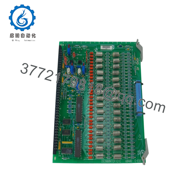
Several parameters below vary by installed turbine configuration and revision level. Legacy Mark IV documentation is often site-specific, so verify against cabinet drawings and OEM records before installation. DS3800NTCF1C1C is identified as a GE Mark IV Thermocouple Condition Card used in Speedtronic systems.
| Parameter | Value |
|---|---|
| Manufacturer | GE General Electric |
| Model | DS3800NTCF1C1C |
| Functional Acronym | NTCF |
| Product Type | Thermocouple Condition Card |
| Series | GE Mark IV Speedtronic |
| Assembly Type | DS3800 Modular Assembly |
| Primary Application | Gas and steam turbine control |
| System Function | Exhaust temperature conditioning |
| Card Quantity in System | Up to 13 cards used in architecture |
| Connector Types | 218A4637-P4 and Amp 533002-1 |
| Jumper Switches | 5 |
| Potentiometers | 4 |
| Resistor Network | 1 |
| Availability | Legacy inventory only |
| Warranty | Typically 12 months depending on source |
Technical references identify this card as part of a multi-board temperature management arrangement where multiple thermocouple cards collectively support turbine exhaust temperature calculations.
- DS3800NTCF1C1C
- DS3800NTCF1C1C
4. Product Introduction
GE DS3800NTCF1C1C is a thermocouple condition card designed for the GE Mark IV Speedtronic turbine control platform. It processes temperature-related signals and supports exhaust temperature regulation in steam and gas turbine systems. The board forms part of the temperature protection architecture used in legacy turbine cabinets.
In field deployments of older Speedtronic systems, thermocouple conditioning cards become critical because temperature calculation errors can cascade into shutdown logic and combustor behavior. Engineers usually stay with matching suffix revisions to avoid unexpected commissioning issues.
5. Installation & Configuration Guide
Stage 1: Pre-Installation Preparation (Estimated: 10 minutes)
⚠️ Safety First: Notify operations of planned downtime. Verify process safe state. Apply lockout/tagout procedures. Wait at least 5 minutes for cabinet discharge.
Tools Required
- ESD wrist strap
- PH1 screwdriver
- Fluke 115 multimeter
- Wire labels
- Smartphone for documentation
- Flashlight
- ESD work mat
Data Backup
- Export controller configuration where possible.
- Record cabinet slot positions.
- Photograph all terminal wiring.
- Photograph jumpers and switches.
- Record hardware revision labels.
⚠️ Mark IV systems frequently contain undocumented modifications added during outages over the last twenty years.
Stage 2: Removing the Old Module (Estimated: 5 minutes)
- Remove cabinet access cover.
- Label all connectors.
- Disconnect carefully. Do not pull on wires.
- Release board retention tabs.
- Pull card straight outward.
- Inspect connectors and backplane areas.
⚠️ Keep the original board nearby.
I’ve watched technicians remove boards and immediately send them to repair. One hour later they realized nobody documented jumper locations.
Stage 3: Installing the New Module (Estimated: 10 minutes)
- Wear ESD protection.
- Verify exact model and suffix: DS3800NTCF1C1C
- Configuration Clone (Crucial): Match jumper and switch positions exactly.
Check:
- Node selections
- Address settings
- Jumper placement
- Hardware revisions
This is the most common rookie mistake, but it happens constantly. Take a picture before you pull it. I can’t stress this enough.
- Insert board slowly into guide rails.
- Confirm connector engagement.
- Reattach hardware.
Self-Checklist
- DIPs match
- Wiring secured
- Tabs locked
Stage 4: Power-On & Testing (Estimated: 10 minutes)
Pre-Power Check
Use a multimeter to verify no short on control power rails.
Power sequence:
- Energize cabinet only
- Observe startup LEDs
- Connect engineering workstation
- Confirm communication status
- Verify temperature values
- Perform dry-run I/O testing
⚠️ Troubleshooting Note: If temperature values appear unstable or communication faults appear immediately, suspect revision mismatch or jumper configuration.
I’ve seen systems throw intermittent temperature alarms for two days because one replacement card used a slightly different revision family.
SOP Quality Transparency
Inbound Inspection & Traceability
- Verify OEM packing data and serial identification.
- Perform anti-counterfeit checks.
- Inspect labels and holograms.
- Inspect for corrosion, scratches, solder rework, and UV aging.
- Verify manuals and documentation.
Live Functional Testing
Testing performed on GE-compatible simulation hardware where available.
Test sequence:
- Power-on self-test
- LED inspection
- Signal verification
- Communication handshake checks
- Temperature simulation
- Continuous operation >24 hours with thermal monitoring
Official test reports generated after testing.
Electrical Testing
- 500 V Megger insulation: >10 MΩ
- Ground continuity test
- Hipot verification where applicable
Firmware & Configuration Verification
- Record firmware information
- Photograph jumper positions
- Archive hardware settings
Final QC
- Inspector sign-off
- ESD bagging
- Bubble wrap protection
- Heavy-duty carton packaging
- QC label with date
Test videos and photos available upon request.
Technical Pitfall & Survival Guide
❗ Firmware Revision Mismatch
Document existing revision data before removal.
I once saw a replacement board jump firmware generations. The turbine controller spent two days generating communication timeout alarms.
❗ DIP Switch / Jumper Errors
Take pictures first.
Simple mistake. Still causes repeated startup delays every year.
❗ Connector and Wiring Assumptions
Even similar GE board families can alter connector assignments.
Never wire from memory.
❗ Power Draw Margin
Leave a minimum 20% power supply capacity margin.
Legacy cabinets accumulate modifications over time.
❗ ESD Damage
Wear grounding protection.
I watched an engineer handle a replacement board during winter without a strap. Powered it up and smoke appeared instantly. Thousands of dollars gone in seconds.
Keep these checks in mind and you’ll save yourself 90% of typical rework time.
6. Frequently Asked Questions (FAQ)
Q1: Can I hot-swap this module?
No.
This board was not designed for insertion under power. Pulling boards live risks backplane damage and can create controller faults.
Q2: Is DS3800NTCF1C1C obsolete?
Yes.
This belongs to GE’s legacy Mark IV Speedtronic family and current availability depends heavily on surplus inventory channels.
Q3: Is this genuinely new or refurbished?
Depends on inventory source.
New Surplus generally means unused older stock. Refurbished means previously installed hardware that passed testing and inspection. Request test reports and actual photos.
Q4: Will replacing this board erase turbine logic?
Normally no.
This board performs signal conditioning. Control logic usually resides elsewhere in the architecture. Still, always create a backup before removal.
Q5: What happens if one card fails?
Mark IV systems may use multiple thermocouple cards in temperature processing. Faulty data can affect exhaust temperature calculations and turbine operation.
Q6: Why are surplus prices lower than GE list pricing?
Inventory age.
Many suppliers purchased stock years ago and now distribute remaining inventory. Lower pricing does not automatically indicate lower quality.
Q7: What is the direct replacement if stock is unavailable?
Use caution.
For Mark IV boards, suffix revisions matter. I strongly recommend matching the exact DS3800NTCF1C1C revision before considering substitutions. Verify against OEM documentation first.


