
 WhatsApp: +86 16626708626
 Email:
  Phone: +86 16626708626
Description
3. Key Technical Specifications
| Parameter | Value |
| Part Number | DS3800XTFW1C1C |
| System | GE Speedtronic Mark IV |
| Input Signals | Low-level logic firing commands |
| Output Type | High-current gate trigger pulses |
| Isolation Rating | Magnetic isolation via pulse transformers |
| On-Board Indicators | Individual channel firing LEDs |
| Connector Type | Multi-pin vertical header and card-edge |
| Revision Level | 1C1C (Verify for backward compatibility) |
| Operating Temp | 0 to 60 °C (32 to 140 °F) |
4. Product Introduction & Supply Chain Strategy
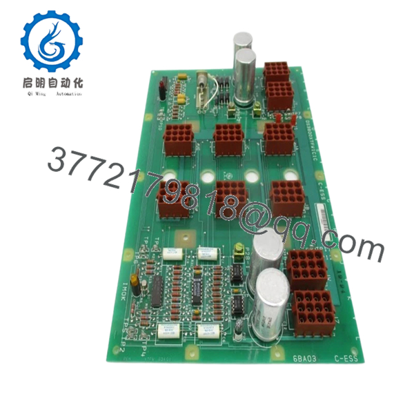
The DS3800XTFW1C1C is a specialized firing board used within the GE Speedtronic Mark IV control system, primarily for managing excitation or power conversion bridges. It acts as the critical interface between low-power logic circuits and high-power thyristors. By using pulse transformers, the board provides the necessary electrical isolation to protect the sensitive control rack from the high voltages present in the power bridge, ensuring precise timing for SCR (Silicon Controlled Rectifier) gating.
From an inventory management perspective, the DS3800XTFW1C1C is a high-risk component. Pulse transformers and capacitors on these boards are subject to aging and insulation breakdown. Securing “New Surplus” units is a strategic necessity because a failure here results in an immediate loss of excitation or power control, leading to a total turbine trip. Relying on refurbished boards for gate-drive circuits is dangerous, as improper pulse timing from a degraded component can lead to catastrophic SCR failure.
5. Installation & Configuration Guide
- Stage 1: Pre-Installation (Prep & Safety): Perform a complete lock-out/tag-out of both the control power and the high-voltage bridge power. Verify zero voltage on the thyristor gate leads. Use an ESD-safe wrist strap.
- Stage 2: Removal: Carefully disconnect any front-facing ribbon cables or wiring harnesses. Loosen the mounting screws and slide the board out, ensuring you do not snag any adjacent wiring.
- Stage 3: Installation (Clone & Seat): Compare the revision suffix and any jumper positions between the old board and the DS3800XTFW1C1C New Surplus unit. Ensure all hardware standoffs are secure to maintain proper grounding.
- Stage 4: Power-On & Testing: Re-apply control power first. Use an oscilloscope (with isolated probes) to verify the firing pulse waveform at the test points before applying bridge power. Confirm that the firing LEDs blink in the correct sequence during the start-up routine.

- DS3800XTFW1C1C
- DS3800XTFW1C1C
6. Firmware/Software Versions & Upgrade Notes
- Hardware Profile: The “XTFW” is a hardware-timed firing board. It does not contain field-loadable firmware.
- Revision Matching: The “1C1C” suffix indicates specific component tolerances and transformer ratings. While often backward compatible with earlier revisions like “1A1A,” always consult your specific GE technical manual to ensure the pulse characteristics match your thyristor gate requirements.
- Replacement Warning: Inconsistent firing pulses can cause “misfiring” in the power bridge, leading to high harmonic distortion or fuse blowing. Never install a board that shows signs of capacitor leakage or transformer discoloration.
7. Frequently Asked Questions (FAQ)
What is the benefit of “New Surplus” over a repaired XTFW board?
Repaired boards often only address the “blown” component. In a firing circuit, the stress of a failure often weakens pulse transformers and optocouplers that may still “test” okay but will fail under load. New Surplus ensures all components have 100% of their original service life.
Is the DS3800XTFW1C1C a hot-swappable part?
Absolutely not. Removing or inserting this board while power is applied can trigger random gate pulses, potentially causing a short circuit in the high-power bridge.
Does this board include the pulse transformers?
Yes, the DS3800XTFW1C1C comes fully populated with the necessary pulse transformers and circuitry required for immediate installation.
How do I know if this board is the cause of my excitation fault?
If you see inconsistent DC output from your bridge or “Gate Drive Fault” alarms on your Mark IV HMI, this board is the primary component to inspect. You can often see the individual firing LEDs on the board to identify a dead channel.


