
 WhatsApp: +86 16626708626
 Email:
  Phone: +86 16626708626
Description
3. Key Technical Specifications
| Parameter | Value |
|---|---|
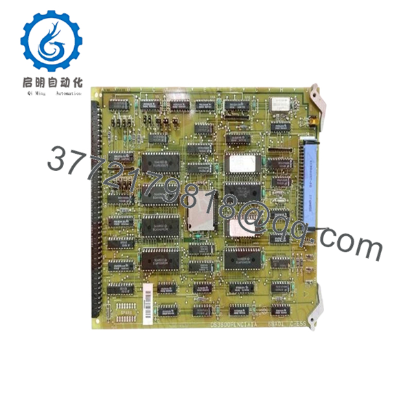
| Model Number | DS3815PLNC1 |
| Manufacturer | General Electric |
| Product Family | GE Speedtronic Mark IV / DS3815 |
| Product Type | PC Board / Control PCB |
| Installation Type | Rack-mounted |
| System Integration | Mark IV backplane architecture |
| PCB Category | Industrial control board |
| Communication Path | Backplane communication interface |
| Operating Environment | Control cabinet installation |
| Operating Temperature | Typically 0 °C to 60 °C* |
| Storage Temperature | −40 °C to +85 °C* |
| ESD Handling | Mandatory |
| Condition | New Original / New Surplus |
| Warranty | 12 months |
*Exact ratings vary by hardware revision and application history. DS3815-series inventory generally exists through legacy surplus channels rather than active OEM production. Current surplus listings identify DS3815PLNC1 as a GE PC board product.
4. Product Introduction
The GE DS3815PLNC1 is an industrial printed circuit control board used in GE legacy turbine and control system environments. Available references classify it as a GE PC board used within older industrial automation architectures and associated control hardware families.
From field experience, DS3815-series hardware typically remains in operation because plants prioritize controlled maintenance over complete migration projects. A planned board replacement often costs substantially less than moving an operating turbine platform to a newer architecture.

- DS3815PLNC1
5. Installation & Configuration Guide
Stage 1: Pre-Installation Preparation (Estimated Time: 10 minutes)
⚠️ Safety First: Notify operations of expected downtime. Verify equipment safe state. Apply lockout/tagout procedures. Remove cabinet power and wait 5 minutes for discharge.
Tools Required
- ESD wrist strap
- PH1 screwdriver
- Fluke 115 multimeter
- Wire labels
- Smartphone for documentation photos
- ESD work mat
Data Backup
- Export any available control backups.
- Record cabinet slot location.
- Photograph connectors and wiring.
- Document jumper positions.
- Label all field wiring.
⚠️ I have opened cabinets where the drawings showed one configuration and the actual installation looked completely different after twenty years of field modifications.
Stage 2: Removing the Old Module (Estimated Time: 5 minutes)
- Remove access covers.
- Label and disconnect wiring.
- Release retaining hardware.
- Pull the board straight outward.
⚠️ Do not twist the card while removing it.
Backplane connectors on older GE systems tolerate very little abuse. One bent pin can create hours of troubleshooting.
- Inspect:
- Connector pins
- Dust accumulation
- Corrosion
- Heat discoloration
- Loose hardware
⚠️ Keep the old board until startup is verified.
Stage 3: Installing the New Module (Estimated Time: 5–10 minutes)
- Wear ESD protection before handling.
- Verify exact model: DS3815PLNC1
- Configuration Clone (Crucial): Duplicate jumper and switch positions exactly.
- Align with guide rails.
- Insert evenly until fully seated.
- Reconnect field wiring.
Self-Checklist:
[ ] Configuration duplicated
[ ] Wiring secured
[ ] Connector fully seated
[ ] Hardware locked
⚠️ This is the most common rookie mistake, but it happens constantly. Take a picture before removal. I can’t stress this enough.
Stage 4: Power-On & Testing (Estimated Time: 10 minutes)
Pre-Power Check
Use a multimeter to verify no short condition exists on the 24 V rail.
Power-up sequence:
- Energize rack power only
- Observe LED startup sequence
- Verify communications
- Connect engineering workstation if available
- Restore backups if required
- Dry-run I/O testing
Expected status:
- Green RUN = Normal
- Red ERR = Fault
⚠️ Troubleshooting Note:
If communication faults appear immediately after startup, inspect connector seating before assuming hardware failure.
Technical Pitfall & Survival Guide
❗ Firmware Revision Mismatch
This catches maintenance teams constantly.
I once watched a startup drag into a second shift because a replacement board revision behaved differently than the original hardware. Everyone initially blamed field wiring.
Avoidance:
- Document firmware and board revisions
- Request matching revisions during ordering
- Verify compatibility before outage work
❗ DIP Switch / Jumper Errors
Take photos first.
Factory defaults almost never match installed systems.
❗ Connector and Wiring Variations
Even similar GE board families can change connector arrangements.
Verify:
- Wiring diagrams
- Connector orientation
- Shield grounding methods
Never wire from memory.
❗ Power Consumption Margin
Maintain at least 20% spare capacity.
Legacy systems rarely have extra power budget available.
❗ ESD Damage
I watched a board handled during winter conditions without grounding protection. It powered once and immediately failed.
That became a very expensive outage.
Use:
- Grounded wrist strap
- ESD work surface
- Anti-static packaging
Keep these checks in mind and you’ll save yourself 90% of typical rework time.
6. Frequently Asked Questions (FAQ)
Q1: Can I hot-swap GE DS3815PLNC1?
No.
Older GE architectures were not designed for hot insertion. Pulling hardware under power risks backplane damage and unpredictable controller faults.
Remove power first.
Q2: Is DS3815PLNC1 obsolete?
Yes.
Current inventory appears primarily in industrial surplus channels rather than active production catalogs. Available market listings classify it as legacy GE hardware inventory.
Q3: Is this genuinely new inventory?
Usually “New Original” means unused surplus stock.
Ask suppliers for:
- Serial numbers
- Packaging photos
- Functional test reports
- Date codes
Q4: Will replacing the board erase control logic?
Usually no.
Logic storage generally exists elsewhere within system architecture. Still, back up everything before touching hardware.
I’ve seen undocumented site edits surprise experienced engineers.
Q5: Why do prices vary so much?
Because availability is inconsistent.
Current public listings range from industrial surplus inventory to specialist suppliers, and pricing differs dramatically depending on traceability and testing history. Public listings show pricing differences exceeding several thousand dollars.
Q6: How do you inspect and test surplus stock?
Our inspection sequence:
- OEM source verification and traceability review
- Anti-counterfeit inspection
- Visual inspection for scratches, corrosion, UV yellowing, and rework marks
- Functional verification on compatible test hardware where available
- Communication verification
- Insulation resistance testing with 500 V Megger (>10 MΩ)
- QC approval and ESD packaging
Test photos and startup videos are available upon request.
Q7: What exactly does DS3815PLNC1 do?
Public documentation on this model remains limited. Current market references identify it broadly as a GE industrial PC board rather than providing detailed function descriptions. Before installation, verify exact compatibility against site drawings and OEM records.


