
 WhatsApp: +86 16626708626
 Email:
  Phone: +86 16626708626
Description
3. Key Technical Specifications
| Parameter | Value |
|---|---|
| Manufacturer | GE General Electric |
| Model Number | DS3820PSCB1C1B |
| Product Series | Speedtronic Mark IV |
| Product Type | Power Supply Assembly Module |
| Primary Application | Gas and steam turbine control systems |
| Input Voltage | 80–140 VDC |
| Output Voltages | +5 VDC, +15 VDC, -15 VDC |
| Typical Output Power | Approximately 60 W |
| Power Distribution | Rack backplane supply distribution |
| Mounting Method | Mark IV rack-mounted assembly |
| Cooling Method | Natural / forced cabinet air circulation |
| Connector Style | Multi-pin industrial backplane connectors |
| Operating Temperature | Typically -20 °C to +70 °C |
| Protection Features | Fuse and circuit breaker protection |
| System Compatibility | GE Mark IV Speedtronic systems |
| Housing Type | Metal enclosed chassis |
| Availability | Limited surplus inventory |
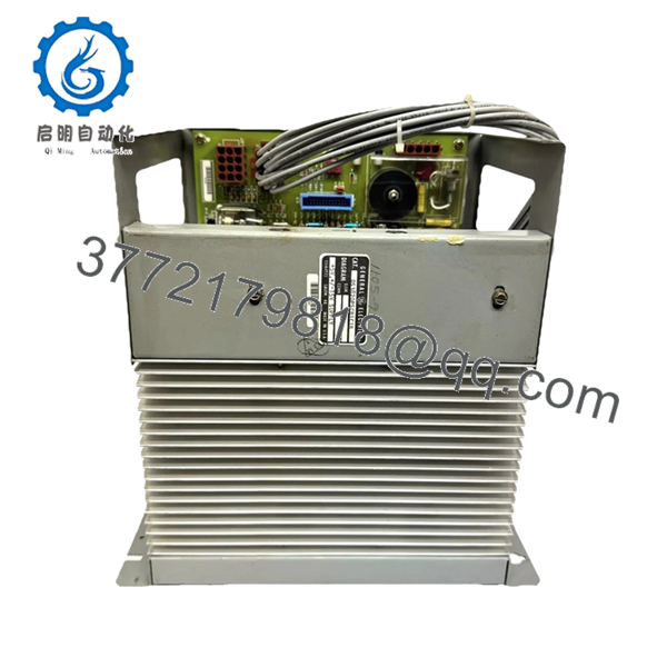
The DS3820PSCB1C1B is identified as a GE Mark IV power supply assembly designed to provide regulated +5 V and ±15 V outputs for turbine control racks and associated control electronics.
4. Product Introduction
The GE DS3820PSCB1C1B is a rack-mounted power supply assembly used in GE Speedtronic Mark IV gas and steam turbine control systems. The module converts incoming DC power into regulated +5 VDC and ±15 VDC outputs required by Mark IV processor boards, I/O assemblies, and communication hardware.
In operating turbine environments, the DS3820PSCB1C1B is considered a critical infrastructure component because unstable rack power causes nuisance trips, communication failures, and intermittent controller faults that are notoriously difficult to diagnose. Plants maintaining legacy Mark IV systems typically keep spare power modules onsite to reduce outage duration.
5. Installation & Configuration Guide
Stage 1: Pre-Installation Preparation (Estimated Time: 10 Minutes)
⚠️ Safety First
- Notify operations and turbine supervision personnel of planned downtime.
- Verify the turbine is fully shut down and isolated safely.
- Apply lock out/tag out (LOTO) procedures to all cabinet power feeds.
- Wait a minimum of 5 minutes for capacitor discharge.
Tools Required
- Grounded ESD wrist strap
- PH1 screwdriver
- Fluke 115 multimeter or equivalent
- Wire labels
- Smartphone for cabinet photos
- Flashlight for rack inspection
Data Backup
- Record cabinet power readings before shutdown.
- Photograph:
- Power supply wiring
- Fuse locations
- Connector orientation
- Rack slot position
- Document existing alarms and PSU LED states.
❗ Always photograph the wiring before removal. I’ve seen experienced techs reverse a DC feed after a long outage shift because two wires looked identical under cabinet lighting.
Stage 2: Removing the Old Module (Estimated Time: 10 Minutes)
- Open cabinet access panels carefully.
- Verify incoming power is isolated completely.
- Label all connectors before disconnecting.
- Remove retaining hardware or mounting screws.
- Pull the module straight out evenly.
- Inspect:
- Backplane connectors
- Fuse holders
- Wiring insulation
- Heat discoloration
- Capacitor leakage
⚠️ Important Note
Do not throw the old unit aside immediately. Use it as a reference for connector orientation, fuse ratings, and mounting configuration during startup.
Stage 3: Installing the New Module (Estimated Time: 10–15 Minutes)
Installation Steps
- Wear grounded ESD protection before touching the module.
- Verify the exact model number:
- DS3820PSCB1C1B
- Confirm input voltage compatibility with the installed cabinet supply.
- Inspect the replacement unit for shipping damage or loose hardware.
- Configuration Clone (Crucial):
- Match fuse ratings exactly
- Verify all jumper settings if present
- Confirm grounding straps are installed correctly
- Insert the module carefully into the rack.
- Secure mounting hardware fully.
- Reconnect all power and signal connectors.
Self-Checklist
- Model verified
- DC input confirmed
- Grounding secure
- Connectors seated fully
- Mounting hardware tightened
❗ Power modules fail prematurely when airflow is blocked. I’ve opened cabinets where someone bundled spare cables directly over the ventilation openings. Six months later the capacitors were cooked.
Stage 4: Power-On & Testing (Estimated Time: 15 Minutes)
Pre-Power Check
- Verify no short exists on the DC input rail.
- Check cabinet grounding continuity.
- Confirm fuse ratings match the original assembly.
- Verify connector polarity before energizing.
Power-On Steps
- Energize the rack without enabling field devices initially.
- Observe startup LEDs and breaker status.
- Measure output voltages using a calibrated multimeter:
- +5 VDC
- +15 VDC
- -15 VDC
- Verify stable communication between rack modules.
- Monitor cabinet temperature and PSU stability during initial load.
- Perform dry-run I/O verification before turbine startup.
⚠️ Troubleshooting Note
If the rack powers partially but CPUs fail to initialize properly:
- Check the +5 V rail first
- Verify connector seating
- Inspect for overloaded power draw
- Confirm no shorted downstream I/O modules exist
I’ve seen one failed analog card drag an entire Mark IV power supply into unstable operation. The PSU looked defective, but the actual fault was downstream.
Quality Control & Testing Procedure
1. Inbound Inspection & Traceability
Each DS3820PSCB1C1B module undergoes:
- OEM label verification
- Serial number traceability review
- Anti-counterfeit inspection
- Visual inspection for capacitor swelling, corrosion, solder rework, and heat damage
- Connector and fuse holder inspection
2. Live Functional Testing
Testing is performed using GE Mark IV-compatible rack hardware whenever available.
Procedures include:
- Controlled power-up testing
- Output voltage verification
- Backplane communication testing
- Load simulation testing
- Continuous energized runtime testing exceeding 24 hours with thermal monitoring
Test videos and voltage measurement photos are available upon request.
3. Electrical Parameter Testing
- 500 V insulation resistance testing (>10 MΩ target)
- Ground continuity verification
- Output ripple measurement
- DC rail stability verification using calibrated Fluke instruments
4. Firmware & Configuration Verification
- Hardware revision documentation
- Fuse and jumper configuration recording
- Connector integrity verification
5. Final QC & Packaging
- QC technician sign-off
- Anti-static ESD packaging
- Shock-resistant bubble wrapping
- Heavy-duty corrugated export carton
- QC Passed labeling with inspection date
- DS3820PSCB1C1B
6. Frequently Asked Questions (FAQ)
Q1: Can the DS3820PSCB1C1B be hot-swapped?
No.
This module powers critical Mark IV rack electronics. Pulling it under load can crash the control rack or damage downstream boards. Shut the cabinet down completely before replacement.
Q2: What voltages does this power supply provide?
The DS3820PSCB1C1B provides regulated +5 VDC, +15 VDC, and -15 VDC outputs used by Mark IV control electronics and associated rack hardware.
Q3: Is this model obsolete?
Yes.
The DS3820PSCB1C1B belongs to the legacy GE Speedtronic Mark IV platform, which has been discontinued for many years. Most available inventory today comes from surplus stock, strategic plant spares, or tested refurbishment channels.
Q4: What is the most common installation problem with these power supplies?
❗ Incorrect input voltage wiring.
I’ve seen technicians assume the cabinet feed matched the replacement unit without checking the actual DC input range. One reversed polarity incident destroyed two connected boards instantly.
Always meter the incoming supply before energizing.
Q5: Why does firmware compatibility matter for a power supply module?
The PSU itself does not contain application logic in the same way CPUs do, but hardware revision compatibility still matters.
Different Mark IV rack revisions sometimes have slightly different loading behavior, connector arrangements, or startup timing characteristics. Always compare hardware revisions before installation.
Q6: Why are old Mark IV power supplies failing more often now?
Mostly capacitor aging and thermal stress.
These systems often operated continuously for decades in high-temperature turbine cabinets. Electrolytic capacitors dry out over time, ripple increases, and voltage stability degrades gradually before outright failure.
Intermittent faults are common during early failure stages.
Q7: Why are some surplus DS3820PSCB1C1B modules priced far below others?
Usually because of condition differences.
Pricing depends on:
- Tested versus untested status
- New surplus versus repaired condition
- Capacitor condition
- Rack test verification
- Cosmetic and connector condition
- Availability of traceability records
If a seller cannot provide actual test results, voltage measurements, or clear photos, proceed carefully.
Keep these checks in mind and you’ll avoid most of the expensive troubleshooting sessions that happen during legacy turbine control outages.


