
 WhatsApp: +86 16626708626
 Email:
  Phone: +86 16626708626
Description
3. Key Technical Specifications
| Parameter | Value |
|---|---|
| Input Voltage | 100–240V AC (47–63 Hz) or 125V DC |
| Input Current | 1.5A max at 120V AC |
| Output Voltage | +24V DC nominal |
| Output Current | 5.0A continuous, 7.5A peak (10 sec) |
| Output Power | 120W continuous max |
| Ripple & Noise | <100 mV peak-to-peak at full load |
| Line Regulation | ±0.5% |
| Load Regulation | ±1.0% (0% to 100% load) |
| Efficiency | 78% typical |
| Hold-up Time | 30 ms at full load |
| Isolation | Input to output: 1500V AC, Output to chassis: 500V DC |
| Overcurrent Protection | Foldback current limiting at 6.5A |
| Overvoltage Protection | Crowbar at 28V ±0.5V |
| Operating Temp | 0 to +55°C (32 to 131°F) |
| Storage Temp | -40 to +85°C (-40 to 185°F) |
| Dimensions | 8.5 x 5.5 x 1.8 inches (approx) |
| Connectors | 1 x 20-pin header, 1 x terminal block (input), 1 x LED status |
| Status LEDs | DC OK (green) |
| GE Part Family | DS3820 (Mark IV) |
4. Product Introduction
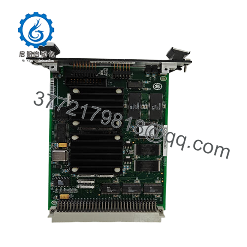
The GE DS3820PSSA1A1A is the PSSA auxiliary power supply board for Mark IV Speedtronic turbine control systems. This board provides isolated +24V DC power to field I/O devices, contact inputs, relay outputs, and solenoid drivers. Unlike the main NPSR board (which powers the rack logic), the PSSA handles external field devices.
You’ll find this board in the lower section of Mark IV I/O racks or in standalone power distribution panels. The 24V output drives thermocouple multiplexers, pressure transmitters, and valve positioners. The PSSA includes foldback current limiting and overvoltage crowbar protection — critical when field wiring shorts occur. If your field devices drop out but the rack logic stays running, suspect this board.
- DS3820PSSA1A1A
5. Troubleshooting Quick Reference
| Symptom | Possible Cause | Relevance to this Part | Quick Check Method | Recommendation |
|---|---|---|---|---|
| Green LED off, no 24V output | Input power missing or internal fuse blown | ✅ High | Measure input at terminal block: 120V AC L-N or 125V DC +/-. | Check upstream breaker. Replace PSSA if input present but no output. |
| Green LED flashing intermittently | Overload or short on 24V output | ✅ High | Disconnect all field wiring from 24V output terminals. Measure resistance to ground — below 20 ohms indicates short. | Find and clear the field short. The PSSA will recover automatically if overload clears. |
| 24V output measures 18V or lower | Overload or regulator failure | ✅ High | Measure output voltage under load (field devices connected). Then disconnect load and measure again. | If voltage returns to 24V with no load, field load exceeds 5A. If still low, replace PSSA. |
| Field devices work but reset randomly | Ripple too high or thermal intermittent | ✅ High | Monitor 24V with oscilloscope while exercising field outputs. Ripple >200mV causes digital input flicker. | Replace PSSA. Capacitor aging is the usual cause. |
| Board hot to touch, smells | Shorted output filter capacitor | ✅ High | Power off. Measure resistance from 24V+ to 24V- (board removed). Below 50 ohms indicates short. | Replace immediately. Do not attempt field repair. |
| No 24V but green LED on | Output connector loose or broken trace | ✅ High | Measure voltage directly at the output terminal block. If present at terminal but not at load, check wiring. | If voltage missing at terminal but LED on, internal connection failed. Replace board. |
| Turbine I/O rack shows “Field Power Fail” alarm | PSSA output dropped below 20V | ✅ High | Check PSSA LED and measure output voltage during alarm condition. Log if voltage sags under load. | Replace preemptively. The crowbar circuit may be triggering falsely. |
Tech Note: The PSSA board uses a switching power supply design. Unlike the linear NPSR, the PSSA makes audible high-frequency whine under heavy load. A little whine is normal. Loud buzzing or chirping indicates failing magnetics — replace it.
6. Frequently Asked Questions (FAQ)
Q: Is the DS3820PSSA1A1A compatible with all Mark IV I/O racks?
A: Yes. This board fits any Mark IV rack that uses a 24V field power supply. That includes the standard P1, P2, and P3 I/O racks. Some early racks (pre-1985) used a different 24V supply — the PSSA is a direct form-fit-function replacement. Check your existing board’s mounting hole pattern. If it has four mounting screws in a rectangle, the PSSA drops right in.
Q: Can I use the PSSA to power non-GE 24V devices?
A: Yes, but respect the 5A continuous limit. The PSSA is a standard 24V power supply with overcurrent protection. You can drive any 24V DC load — sensors, relays, small solenoids, or even a 24V LED light. Just don’t exceed 5A. The foldback current limiting will drop output voltage to near zero if you short it, but it recovers automatically.
Q: Why does my PSSA keep blowing the input fuse?
A: Two likely causes. First, you have a shorted input MOV (metal oxide varistor) from a previous surge event. The MOV fails shorted, blowing the fuse instantly. Second, the input bridge rectifier or switching FET failed shorted. Either way, board replacement is the fix. These aren’t field-serviceable without a rework station and schematics.
Q: What’s the difference between PSSA and PSSB or PSSC revisions?
A: Revision tracking:
- PSSA (DS3820PSSA1A1A): Original design, no conformal coating.
- PSSB (DS3820PSSB1A1A): Added input surge suppression and conformal coating.
- PSSC (DS3820PSSC1A1A): Added wider input voltage range (85–264V AC).
The PSSA works in all applications unless your site has severe power quality issues (frequent surges, lightning strikes). For coastal or high-humidity environments, use PSSB or PSSC.
Q: Can I bench test the PSSA without a Mark IV rack?
A: Absolutely. Apply 120V AC to the input terminal block (L, N, G). The green LED should light immediately. Measure output voltage between the two output terminals — should be 24V DC ±5%. No load required. If you have a 50W, 10 ohm resistor (or a 24V automotive bulb), connect it as a load. The voltage should stay above 23V at 2A draw.
Q: My PSSA output is 24V but my field devices don’t work. What else could be wrong?
A: Check the return path (common/ground). The PSSA output is isolated from chassis ground. Many field devices expect the 24V return to be tied to earth ground at one point. If your system uses a floating 24V return and you have leakage currents, the voltage between 24V- and earth can drift. Measure from 24V- to earth ground. If you see more than 5V AC or DC, bond 24V- to earth at the PSSA terminal block using a ground strap.
Q: What’s your warranty on this obsolete board?
A: 1-year replacement warranty. Covers failure under normal operating conditions — correct input voltage, ambient temperature below 55°C, no physical damage. Does NOT cover damage from water, corrosion, lightning strikes, or incorrect wiring. We test every PSSA on a genuine Mark IV test rack before shipping. Request test data — we’ll provide voltage readings, ripple measurement, and load test results.
Q: Can I replace my failed PSSA with a generic industrial 24V power supply?
A: You can, but we don’t recommend it for three reasons. First, the PSSA mounts on a custom bracket with specific connector alignment. A generic DIN rail supply won’t fit without modification. Second, the PSSA communicates a “Power Good” signal to the Mark IV rack through the backplane. A generic supply lacks this signal, so the rack will show a persistent alarm. Third, the PSSA’s crowbar circuit protects downstream boards during overvoltage. Generic supplies use different protection schemes. If you’re in a pinch, you can hack a generic supply in, but long-term, use the correct board.


