
 WhatsApp: +86 16626708626
 Email:
  Phone: +86 16626708626
Description
Key Technical Specifications
| Parameter | Value |
| Part Number | A20B-2101-0390 (Alternating: A20B21010390) |
| Module Compatibility | FANUC \alpha_i Power Supply Modules (\alpha_iPS) A06B-6140 Series |
| Supported Drive Range | 2 kW to 55 kW high-output configurations |
| Output Phase | Three-Phase output matching \alpha_iSV and \alpha_iSP systems |
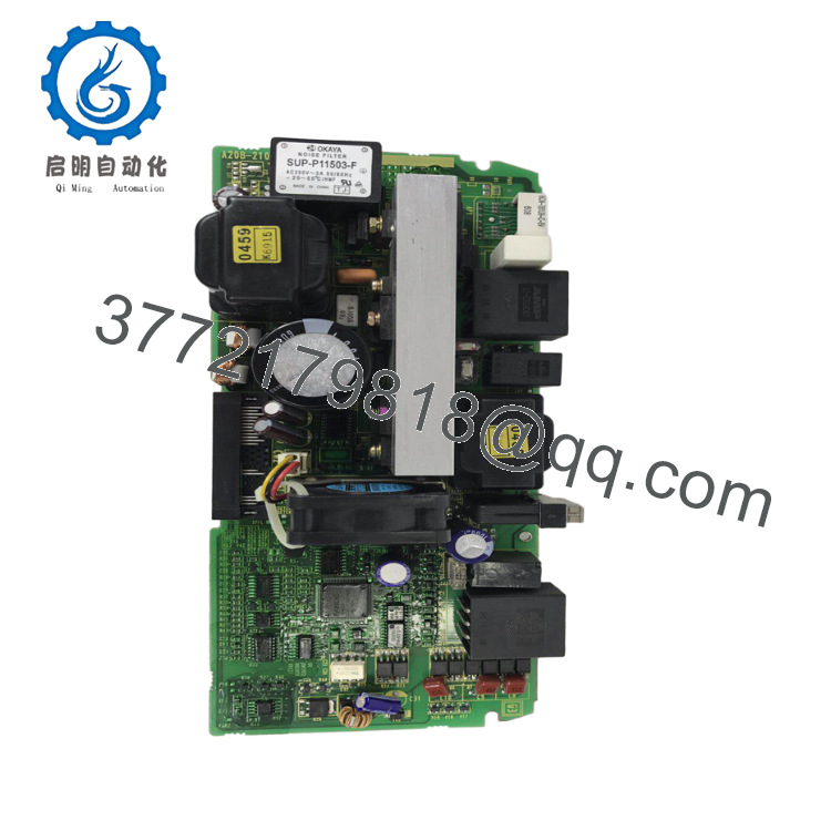
| Onboard Display | Integrated 7-segment diagnostic LED assembly |
| Suppression Hardware | High-attenuation integrated power noise filter |
| System Voltage Class | 200 VAC auxiliary command input loops |
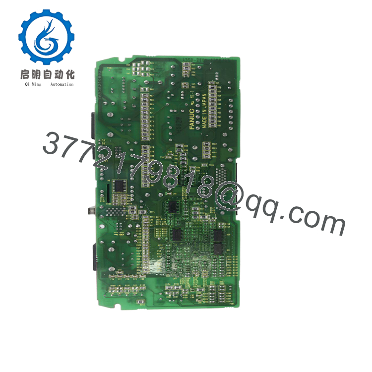
| Circuit Type | Double-sided surface mount power control PCB |
| Weight | 1.0 kg (2.2 lbs) |
Product Introduction & Supply Chain Strategy
The GE Fanuc A20B-2101-0390 is a high-reliability power control circuit board designed exclusively for the FANUC Alpha i (\alpha_iPS) A06B-6140 series power supply modules. This card handles internal power regulation, communication sequencing, and command handshakes between the CNC system and connected servo (\alpha_iSV) or spindle (\alpha_iSP) drives. Equipped with an integrated 7-segment diagnostic LED display and an onboard electromagnetic noise filter, this PCB delivers clean, stable electrical performance to maintain signaling precision during heavy machining tasks.
Sourcing this specific power supply PCB as New Surplus is a calculated method to lower your facility’s Total Cost of Ownership (TCO). Because components inside automated CNC platforms degrade from continuous thermal cycling and high switching frequencies, using standard refurbished cards increases the risk of early circuit breakdown and line tracking faults. Furthermore, because sub-assembly components are rarely sold as separate lines by the primary OEM, long marketplace lead time variability can halt lines for weeks. Storing an original, factory-sealed surplus unit as buffer stock allows technicians to repair modular faults immediately, avoiding high emergency shipping costs or the huge capital required for entire system replacement.
Installation & Configuration Guide
Stage 1: Pre-Installation (Prep & Safety)
- Shut down the machine tool interface. Enforce full lock-out/tag-out (LOTO) protocols on the primary three-phase 200/480 VAC breaker feeding the drive cabinet.
- Allow a minimum of 20 minutes for internal drive capacitors to discharge completely. Use a calibrated multimeter to check for zero voltage at all DC bus terminals (L+ and L-) before servicing.
- Secure a grounded ESD wrist strap around your arm and attach it to the bare metal cabinet framework to prevent static damage to the surface-mount logic.
- Take reference photographs of all top ribbon cables and ground straps connected to the control card faceplate.
Stage 2: Removal
- Gently unplug the front communication and internal command ribbon cables from their header seats. Do not bend the pin matrices.
- Remove the plastic cover shield housing and loosen the retaining screws holding the A20B-2101-0390 card to the primary module sub-base.
- Pull the board straight out out from its internal guide channels, taking care not to scrape the rear traces against adjacent copper bus lines.
- Seal the removed PCB inside an antistatic containment bag immediately.
Stage 3: Installation (Clone & Seat)
- Verify that all jumper pins and hardware configuration points on the new surplus A20B-2101-0390 exactly replicate the settings of the card you just removed.
- Slide the replacement board along the internal module tracks until the rear header sockets align properly with the underlying wiring board plugs.
- Tighten the retaining screws securely to ground the card chassis, preventing contact looseness caused by axis movement vibrations.
- Carefully reconnect all internal ribbon interfaces back to their corresponding terminal headers.
Stage 4: Power-On & Testing
- Disconnect the main spindle and servo axis high-power circuits, allowing only auxiliary control loop power to feed the card interface.
- Re-energize the CNC control system. Monitor the integrated 7-segment LED display immediately upon initialization.
- The alphanumeric window must read standard boot codes without outputting an alarm fault or lighting up the red fault indicator.
- Connect your CNC diagnostic system to verify communication with the master processor block before restoring full high-voltage three-phase lines for machining operations.

- A20B-2101-0390
- A20B-2101-0390
Firmware/Software Versions & Upgrade Notes
The A20B-2101-0390 power control card contains specific factory boot parameter ICs that manage communication sequencing with alpha drive lines. Using an incompatible card revision level (such as pairing older generation circuit layers with newer high-power software blocks) can trigger instantaneous DC bus synchronization timeouts.
Prior to re-mounting hardware setups, confirm the baseline manufacturing suffix code (e.g., /08A) stamped on the board perimeter aligns with your system engineering blueprints. Do not attempt to exchange firmware ROM chips between different board configurations, as variations in trace layers can cause immediate controller failures.
Frequently Asked Questions (FAQ)
Q: Why choose a New Surplus A20B-2101-0390 card over standard third-party refurbished items?
A: Refurbished power boards carry real, unmeasured secondary failure risks. While a repaired card might pass basic bench validation, its underlying solid-state logic has already logged thousands of running hours under intense thermal strain. A failure on a second-hand part can cause major secondary damage, such as shorting out your main servo motors or spindle drives and generating thousands of dollars in unplanned machinery downtime.
Q: Is this board sold separately by the OEM, or must I purchase a complete drive module assembly?
A: FANUC typically supplies the A06B-6140 power module as a complete single hardware unit rather than selling the control PCB on its own. Sourcing this individual board as New Surplus allows you to swap out damaged control logic or failed communication components on-site, bypassing the need to pay for an entire high-voltage housing block.
Q: What is the purpose of the 7-segment LED display integrated directly on the PCB body?
A: The display provides real-time diagnostic readouts and fault status reports. It allows maintenance teams to quickly pinpoint internal power faults, DC bus overvoltage situations, or communication errors without needing to connect external diagnostic software to the CNC panel.
Q: Will the board retain its tuning metrics and memory configurations when placed in long-term warehouse storage?
A: Yes. System-specific drive tuning parameters are managed directly by the main CNC controller unit, while baseline power tracking algorithms are stored in non-volatile memory chips on the PCB. The board can remain in warehouse storage for years without losing configuration data or needing an internal battery pack.
Q: What kind of warranty program protects this surplus module?
A: We cover this new surplus item with a comprehensive 12-month operational warranty starting from your delivery date. This guarantees the card will function identical to factory-new standards, giving your site engineering teams total confidence when backing up vital CNC production machinery.



