
 WhatsApp: +86 16626708626
 Email:
  Phone: +86 16626708626
Description
3. Key Technical Specifications
| Parameter | Specification |
|---|---|
| Manufacturer | GE Fanuc / Emerson Automation Solutions |
| Part Number | IC200ALG327H |
| Product Line | VersaMax I/O / PLC System Platform |
| Number of Channels | 4 analog output channels |
| Output Signal Ranges | Current: 4 to 20 mA, 0 to 20 mA | Voltage: 0 to 10 Vdc, ±10 Vdc, 1 to 5 Vdc, 0 to 5 Vdc |
| Converter Resolution | 12-bit binary converter layout |
| Output Update Rate | Less than 5 ms for all 4 channels |
| Internal Power Consumption | 30 mA maximum @ 5 Vdc backplane logic rail |
| External Power Requirement | 24 Vdc nominal loop supply (19.2 to 30 Vdc range), 110 mA maximum consumption |
| Load Impedance (Current) | Supports up to 850 ohms maximum load at 24 Vdc external supply |
| Load Impedance (Voltage) | Requires 2,000 ohms minimum load resistance |
| Isolation Barrier | 250 Vac continuous / 1,500 Vac for 1 minute (field-to-logic) |
| Diagnostics Indicators | 1x INT LED (Green = Internal logic and backplane power are normal) |
4. Product Introduction & Supply Chain Strategy
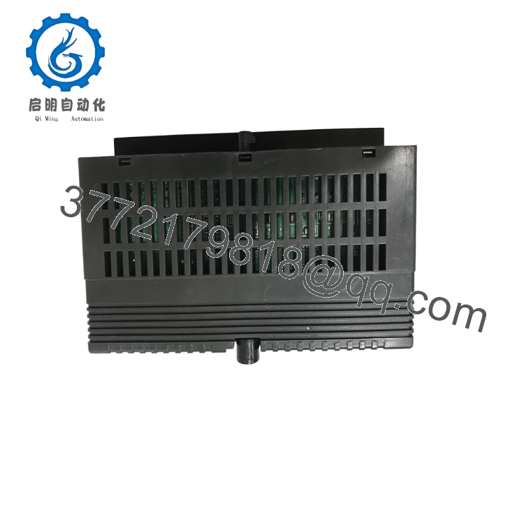
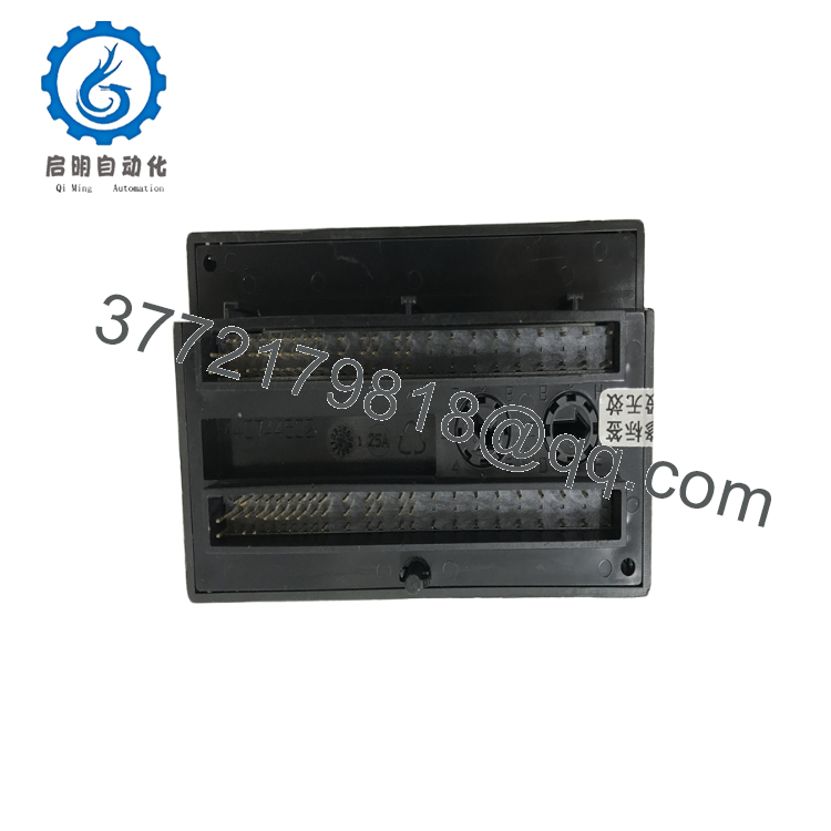
The GE VersaMax IC200ALG327H is a 4-channel, 12-bit analog output module designed to deploy directly into standard VersaMax PLC rack assemblies or distributed network interface units (NIUs). This module converts raw digital CPU register values into precise, repeatable analog loop signals, supporting multiple field ranges including 4–20 mA current loops and 0–10 Vdc voltage spans. It acts as the primary governor for modulating field devices, managing proportional control valves, variable frequency drive (VFD) speed loops, I/P transducers, and graphical panel meters.
From an inventory control and capital efficiency perspective, stocking the IC200ALG327H as New Surplus provides an exceptional security policy for high-value operations. Relying on refurbished analog output cards introduces significant Total Cost of Ownership (TCO) vulnerabilities. Used modules often suffer from component degradation in their digital-to-analog converters (DACs) and field isolation barriers, which can cause subtle calibration drift, signal clamping, or severe channel-to-channel crosstalk. Such flaws can lead to erratic valve hunting or unstable motor profiles. This factory-sealed New Surplus module delivers true zero-hour OEM precision, preserving continuous line stability.

- IC200ALG327H
- IC200ALG327H
5. Installation & Configuration Guide
Stage 1: Pre-Installation (Prep & Safety)
- System Power Isolation: Completely de-energize the targeted VersaMax rack framework. Lock out and tag out all external 24 Vdc auxiliary loop feeds. Confirm zero voltage across all terminal connections using a digital multimeter.
- Carrier Mechanical Keying: Inspect the companion IC200CHSxxx terminal carrier base. Ensure the integrated mechanical keying index dial is matched for an analog output profile to prevent hardware damage upon insertion.
- ESD Protocol: Fasten a grounded ESD wrist strap before handling the replacement module to safeguard the internal 12-bit converter semiconductors from static breakdown.
Stage 2: Removal
- Latch Release: Press inward firmly on the flexible plastic release tabs located at the top and bottom edge flanges of the card housing.
- Module Extraction: Slide the module straight away from the terminal carrier base. Avoid rocking or twisting motions that might strain or bend the internal backplane connector pin matrix.
- Base Inspection: Check the empty slot contacts for debris or localized oxidation before seating the replacement unit.
Stage 3: Installation (Clone & Seat)
- Module Seating: Align the housing guide tracks with the corresponding slots on the pre-wired terminal carrier base. Press the IC200ALG327H firmly onto the base until both the top and bottom locking clips snap shut.
- Software Configuration Verification: Open your project files within Proficy Machine Edition. Double-check that individual slot parameters (such as 4–20 mA vs. 0–10 V output ranges) match the exact wiring layout of your active field devices.
Stage 4: Power-On & Testing
- Initial Power Application: Re-energize the external 24 Vdc auxiliary loop supply, then apply primary power to the rack backplane assembly.
- LED Diagnostics Audit: Confirm the faceplate “INT” LED illuminates solid green, indicating a successful power-on self-test.
- Loop Calibration Validation: Use your programming software to force an analog register value (e.g., 50% scale or 2048 counts). Measure the output at the terminal strip using a digital multimeter to verify it yields exactly 12.0 mA or 5.0 Vdc.
6. Firmware/Software Versions & Upgrade Notes
The IC200ALG327H utilizes a dedicated internal analog execution array and a pre-programmed microcontroller microcode stack rather than flash memory that requires periodic field updates. Hardware versions are tracked by the suffix designator stamped onto the PCB housing (with version H denoting specific optimizations for enhanced noise immunity over earlier A-G iterations).
When integrating a New Surplus “H” revision board into older legacy panels, ensure your VersaMax CPU or communications module (such as the IC200BEM003 Profibus interface) is running firmware v1.50 or higher. Early CPU firmware baselines can occasionally flag initialization errors when encountering newer hardware revisions. If a firmware update of the primary controller is not feasible during the maintenance window, the module can be addressed via generic analog configuration blocks.
7. Frequently Asked Questions (FAQ)
- Why should I purchase a New Surplus IC200ALG327H over a refurbished unit? A refurbished module is a used component that carries hidden thermal strain from its previous service life. Over time, internal optocouplers and resistor networks age, causing signal drift that affects valve positioning or motor speeds. This New Surplus card delivers zero operational hours, pristine 1,500 Vac field-to-logic isolation boundaries, and factory-original 12-bit calibration accuracy.
- Can I output both voltage and current commands from the same card simultaneously? Yes. The IC200ALG327H allows you to configure individual channels independently within your PLC programming software (such as Proficy Machine Edition). For example, you can set Channel 1 to deliver a 4–20 mA current command to a positioner while setting Channel 2 to supply a 0–10 Vdc speed reference to a drive.
- Does this analog output card require external auxiliary power to run? Yes. While the module draws a small 30 mA logic supply from the 5 Vdc PLC backplane rail, driving the physical analog loops requires a separate, external 24 Vdc auxiliary power source connected directly to the carrier base terminals. This loop supply can draw up to 110 mA depending on load conditions.
- Is it safe to hot-swap this module while the system is under power? The VersaMax platform physically allows I/O modules to be hot-swapped while the rack backplane is energized, provided the terminal carrier base remains securely mounted. However, removing an analog output card during live operation will instantly cut power to all four control loops, causing connected valves or drives to drop to their default fail-safe states, which may disrupt your process.
- What does a dark “INT” LED on the front panel indicate? The “INT” (Internal) LED indicates the health of the module’s onboard logic. If it remains unlit when the PLC rack is powered, it suggests either a lack of 5 Vdc logic power from the backplane, an unseated module connection, or an internal hardware failure that caused the board to fail its power-on self-test.



