
 WhatsApp: +86 16626708626
 Email:
  Phone: +86 16626708626
Description
3. Key Technical Specifications
| Parameter | Value |
| Circuit Type | Solid-state diode steering array / Rectifier assembly |
| Target Systems | GE Speedtronic Mark VI Steam/Gas Turbine Systems & EX2100 Excitation Systems |
| Enclosure/Form Factor | Small rectangular card format, open PCB layout without an external faceplate |
| Mounting Hardware | Drilled corner mounting pads with conductive traces; dual auxiliary bracket screw points |
| Onboard Auxiliary Card | Mid-board mounted expansion card with dedicated FPGA, logic ICs, and transistors |
| Signal Connections | Multi-point terminal blocks and pin-header connections |
| Component Layout | Heavy-duty power diodes, high-stability resistors, filter capacitors, and test points |
| Cooling Profile | Natural convection cooling inside a ventilated rack structure |
| Diagnostic Features | Onboard probe test points for manual diode validation and multi-meter checks |
4. Product Introduction & Supply Chain Strategy
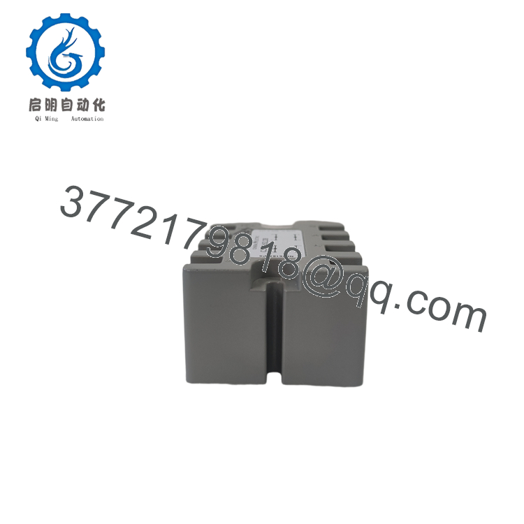
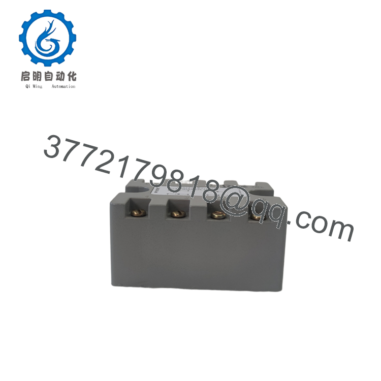
The GE IC3500A452L208 is a specialized, multi-function diode terminal block and rectifier board assembly engineered for GE’s legacy Speedtronic Mark VI gas/steam turbine control and EX2100 static excitation systems. Built to survive the harsh electrical environments of power plants and industrial maritime engine rooms, this board features a heavy-duty diode matrix designed to steer high-integrity signal loops, suppress electrical feedback, and rectify control-loop voltages. Rather than a basic passive block, it houses a centralized daughterboard containing a field-programmable gate array (FPGA) and discrete transistors to handle localized, high-speed switching feedback logic.
For control engineers and procurement leads, sourcing a certified New Surplus IC3500A452L208 is a crucial risk-management strategy. Because the Speedtronic Mark VI and early EX2100 platforms are obsolete, a failures on a diode or feedback bus can immediately trigger a turbine trip or generator excitation shutdown. Third-party repaired boards often feature underlying thermal fatigue on the copper traces or degraded semiconductor junctions. Maintaining a zero-hour, factory-original surplus card on-site ensures your plant can recover from failure in minutes rather than facing catastrophic outages and high emergency sourcing premiums.

- IC3500A452L208
- IC3500A452L208
5. Installation & Technical Verification
Stage 1: Pre-Installation Prep
Ensure the turbine control panel is entirely isolated from active power. Perform lock-out/tag-out (LOTO) protocols on the primary 125 VDC control bus and any auxiliary 120/240 VAC power feeds. Fasten a grounded ESD wrist strap before handling the replacement card to prevent static damage to the sensitive onboard FPGA and CMOS logic gates.
Stage 2: Mechanical Swap
Verify the physical orientation of the existing IC3500A452L208. Label all landing wires and communication jumpers leading to the screw terminal block channels. Carefully loosen the corner mounting screws from the standoff brackets. Unplug any ribbon cable headers or edge connectors, then gently extract the assembly. Install the new surplus card onto the clean mounting standoffs, securing the screws through the grounded, conductive corner drill holes.
Stage 3: Electrical Commissioning
Carefully land and tighten all terminal block wires back onto the board in accordance with your system’s wiring schematic. Reconnect the header plug assemblies. Before energizing the host panel, use a digital multimeter in diode-test mode to verify the integrity of the critical forward and reverse bias paths across the onboard diode array.
Stage 4: System Integration
Restore control power to the cabinet. Verify that the auxiliary diagnostic card initializes without any fault indicators. Run a system-level check on the PC-based turbine HMI (using GE’s ControlSystem Toolbox or ToolboxST software) to confirm that feedback voltage loop diagnostics are completely clear of ground or open-loop faults.
6. Frequently Asked Questions (FAQ)
What is the role of the auxiliary daughterboard on the IC3500A452L208?
The auxiliary board mounted in the center of the IC3500A452L208 handles localized, high-speed logic and signal conditioning. By utilizing an onboard FPGA, integrated circuit arrays, and transistors, it processes active signal inputs, filters noise, and passes telemetry data back to the primary Mark VI/EX2100 controller rack without taxing the main processing loop.
Can this board be used interchangeably across different Speedtronic systems?
While designed primarily for the Mark VI control architecture and certain EX2100 excitation networks, this board is configured via precise jumper switches, connector assignments, and physical wiring diagrams. Always verify that the hardware part number and revision suffix match the requirements of your specific system layout drawing before putting the unit in service.
Is this GE IC3500A452L208 board a refurbished unit?
This product is a Brand New Surplus unit. It is not used, has not been pulled from a decommissioned asset, and is not a third-party repair. Every unit undergoes strict quality verification, featuring pristine conductive mounting holes, clean trace routing, and unsolder-marked, factory-original components.
What warranty terms apply to this legacy GE component?
We protect this New Surplus IC3500A452L208 module with our comprehensive 1-year operational warranty from your date of purchase. This long-term coverage shields your facility’s maintenance and operating budget from the limited 30-day warranties typically offered by vendors selling used or third-party repaired components.



