
 WhatsApp: +86 16626708626
 Email:
  Phone: +86 16626708626
Description
3. Key Technical Specifications
| Parameter | Specification |
|---|---|
| Manufacturer | GE Fanuc / General Electric (Originally built via Koyo architecture) |
| Part Number | IC610MDL116A |
| Product Line | Series One Programmable Logic Controller |
| Number of Channels | 4 analog input circuits |
| Input Signal Profile | 4 to 20 mA DC analog current loops |
| Module Placement | Consumes 1 standard I/O slot in Series One racks (e.g., IC610CHS100) |
| Wiring Interface | Front-mounted screw terminal strip configuration |
| System Isolation | Optically isolated between field circuits and PLC logic backplane |
| Power Distribution | Receives primary logic supply rails directly from the backplane chassis |
| Compatible Software | Logicmaster 1 / Handheld Programmer configurations |
4. Product Introduction & Supply Chain Strategy
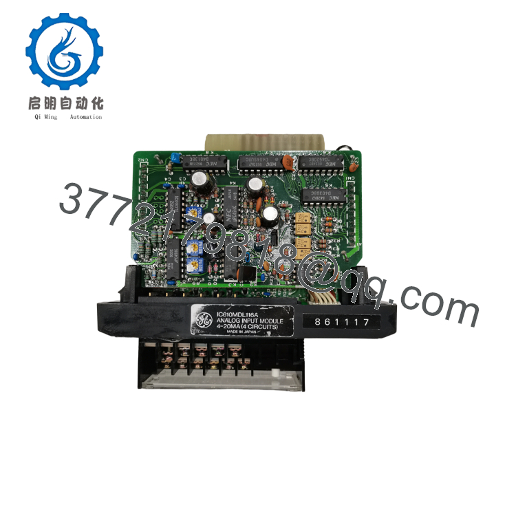
The GE Fanuc IC610MDL116A is a legacy 4-channel analog input module designed for the classic Series One PLC control system. Featuring four isolated input circuits, this card acts as the processing gateway for translating 4–20 mA analog loop signals into the digital memory registers used by the system processor. It handles primary instrumentation loops for vintage machinery setups, monitoring variables like tank levels, pipe pressures, temperature transmitters, and flow rates.
Because the Series One ecosystem has been obsolete for several decades, finding verified New Surplus parts is crucial for protecting your operational continuity. Relying on refurbished analog cards poses a real risk of hidden component wear. Used cards have often logged tens of thousands of hours under thermal load, leading to degraded internal input resistors, worn optocouplers, and signal drift. This drift can cause erratic readings and unexpected system shutdowns. This factory-sealed New Surplus module delivers true original calibration precision and immediate plug-and-play drop-in utility.

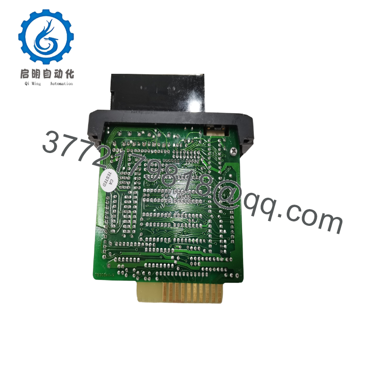
- IC610MDL116A
- IC610MDL116A
5. Installation & Configuration Guide
Stage 1: Pre-Installation (Prep & Safety)
- Chassis De-energization: Shut down the main power feed to the Series One rack assembly. Lock out and tag out the primary cabinet power breaker. Verify that the incoming supply line and all 4–20 mA current loops read 0 V using a digital multimeter.
- Address Mapping Review: Reference your physical layout schematics or handheld programmer address tables to confirm that the assigned slot matches your program’s analog data registers.
- ESD Protocol: Put on a grounded ESD wrist strap before unboxing the card to safeguard the legacy internal components from sudden static discharge.
Stage 2: Removal
- Terminal Disconnection: Carefully label and unscrew the individual field loop wires from the front terminal strip. Gently position the wiring harness to the side.
- Card Extraction: Release the module’s top and bottom retaining mechanisms on the rack. Pull the card smoothly toward you along its slot guide tracks to avoid flexing the chassis frame.
- Slot Audit: Inspect the empty backplane socket pins for dust, debris, or localized corrosion before inserting the replacement card.
Stage 3: Installation (Clone & Seat)
- Module Seating: Align the top and bottom rails of the new New Surplus IC610MDL116A with the target rack tracks. Push the module firmly into the slot until its rear connector pin block seats completely into the backplane bus socket.
- Terminal Hookup: Secure the labeled current loop wires back onto their corresponding front terminal screws, making sure to maintain correct positive (
+) and negative (-) polarity for each circuit.
Stage 4: Power-On & Testing
- Initial Energization: Apply power to the primary Series One rack chassis.
- Logic Handshake Check: Verify that the system CPU starts up without flagging configuration or I/O faults.
- Loop Performance Audit: Use an analog loop calibrator to inject a standard test signal (such as 12.0 mA) into Channel 1. Check your logic registers to verify that the value matches your expected data scaling.
6. Firmware/Software Versions & Upgrade Notes
The IC610MDL116A relies entirely on hardware-driven analog signal processing circuits and does not feature field-upgradable digital firmware or flash memory. System integration is managed entirely by the physical board revision and the matching memory addresses set up through legacy programming tools.
When replacing this card within an active system, make sure your program is configured using Logicmaster 1 software or the physical Series One handheld programming unit. No software modifications are required when replacing a card with the same part number, provided the terminal wiring matches the original channel layout.
7. Frequently Asked Questions (FAQ)
- Why is this card cross-referenced under both GE Fanuc and Koyo? The GE Series One platform was co-developed and manufactured by Koyo, which also sold it under the Texas Instruments TI305 and AutomationDirect DirectLOGIC 305 series. Because of this shared design, the IC610MDL116A is fully interchangeable with these equivalent part numbers, facilitating cross-platform replacements.
- Does this module function as a current loop “source” or “sink”? The IC610MDL116A acts as a current loop receiver. It requires an external 24 Vdc loop power source to drive the current from your field transmitters through the card’s input channels.
- What happens to the system values if a field loop wire breaks? If a 4–20 mA field wire snaps or disconnects, the input current will instantly drop to 0 mA. Because this falls below the normal 4 mA baseline, your PLC program can use this distinct drop to trigger a wire-break diagnostic alarm and put the process into a safe state.
- Can I remove this module from the chassis while the rack power is active? No. The legacy Series One backplane architecture does not support hot-swapping. Removing or inserting a module while the rack is powered can cause electrical arcing across the backplane data pins, risking corruption of the CPU memory or permanent hardware damage. Always turn off the power before servicing.
- How does a New Surplus card protect my system better than a refurbished module? Refurbished analog cards often have aging internal components that can cause measurement drift over time. This calibration drift can lead to inaccurate sensor data and process instability. A New Surplus board provides a zero-hour component with factory-original calibration precision, eliminating the risk of unexpected diagnostic faults.



