
 WhatsApp: +86 16626708626
 Email:
  Phone: +86 16626708626
Description
Key Technical Specifications
- Manufacturer: GE Fanuc Automation
- Part Number: IC670ALG240
- Product Family: Field Control Distributed I/O
- Module Type: 16 Point Grouped Analog Input Module
- Input Channels: 16 single-ended current inputs
- Input Signal Range: 0 to 25 mA
- Typical Signal Type: Current loop transmitters
- Transmitter Compatibility: 2-wire and 3-wire current transmitters
- Resolution: 16-bit analog data format
- Data Types: Word and bit data
- Digital Filtering: Selectable 10 ms or 20 ms filtering
- Calibration Storage: FLASH memory calibration data
- Acquisition Rate: Supports 50 Hz and 60 Hz line frequency settings
- Diagnostics: High/Low alarm, under-range, over-range, open-wire detection
- Configuration: Individual channel configuration
- Communication Interface: Field Control Bus Interface Unit connection
The GE Fanuc IC670ALG240 is a 16-point grouped analog input module for the Field Control distributed I/O system. It accepts 0 to 25 mA current loop signals from two-wire or three-wire transmitters and converts them into digital values for the host PLC processor.
Product Introduction
The GE Fanuc IC670ALG240 is a Field Control analog input module designed for industrial measurement applications requiring multiple current loop inputs. The module provides 16 single-ended analog input channels and interfaces with current transmitters through a distributed I/O architecture.
This module is commonly found in legacy GE Fanuc control systems where maintaining existing Field Control I/O installations is required. It provides channel-level configuration, scaling, filtering, and diagnostic monitoring functions for process instrumentation signals.
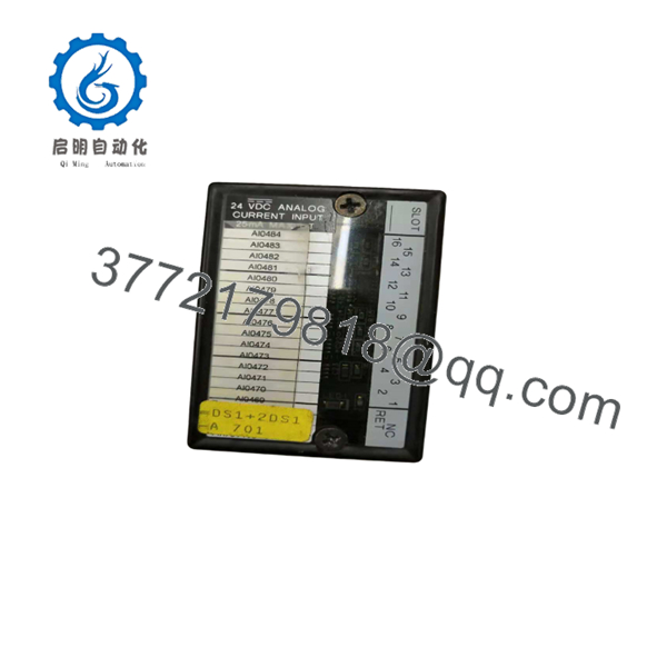
IC670ALG240
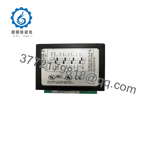
IC670ALG240
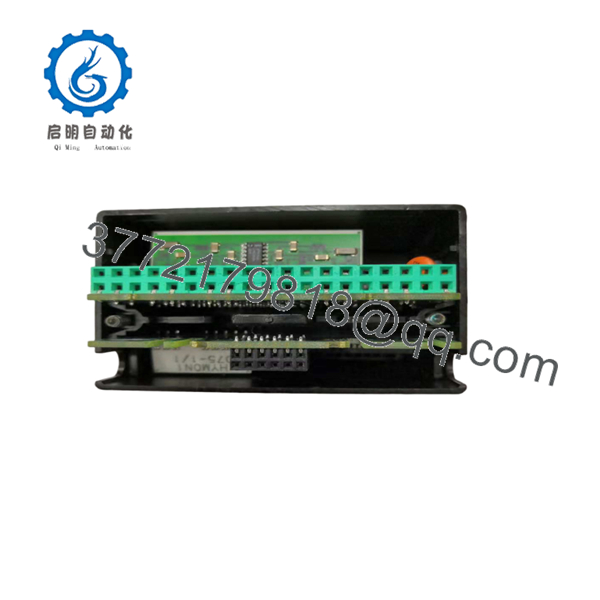
IC670ALG240
Installation & Configuration Guide
Stage 1: Pre-Installation Preparation (Approx. 10 minutes)
⚠️ Safety First
- Notify operations personnel before removing the IC670ALG240 module.
- Place the controlled equipment into a safe condition.
- Apply lockout/tagout procedures before disconnecting field wiring.
- Confirm all external loop power sources are isolated.
Tools Required
- ESD wrist strap
- Phillips screwdriver
- Digital multimeter
- Wire labels
- Smartphone/camera for documentation
Data Backup
Before removal:
- Record the Field Control Bus Interface Unit configuration.
- Document module position and addressing information.
- Photograph all terminal wiring.
- Record channel scaling and alarm parameters.
- Verify transmitter loop power arrangements.
Stage 2: Removing the Old Module (Approx. 10 minutes)
Steps:
- Remove the Field Control terminal block cover if installed.
- Label each analog input wire.
- Disconnect current loop wiring carefully.
- Remove the module from the Field Control base.
- Inspect connectors for contamination, corrosion, or damaged contacts.
⚠️ Note:
Keep the original IC670ALG240 until the replacement has passed signal verification.
Stage 3: Installing the New Module (Approx. 15 minutes)
Steps:
- Wear an ESD wrist strap before handling the module.
- Confirm the replacement part number is IC670ALG240.
- Install the module into the correct Field Control terminal base.
- Reconnect analog loop wiring according to the site drawings.
- Verify current loop polarity before energizing.
Configuration Clone Checklist
- Module type matches original configuration
- Channel assignments verified
- Scaling values copied
- Alarm limits confirmed
- Transmitter wiring checked
Stage 4: Power-On & Testing (Approx. 20 minutes)
Pre-Power Check
- Verify loop power voltage.
- Confirm no wiring shorts exist.
- Check transmitter polarity.
Power-On Steps
- Energize the Field Control station.
- Check module status LED.
- Verify communication with the Bus Interface Unit.
- Confirm analog values appear in the PLC.
- Compare displayed values with field transmitter readings.
- Test alarm limits and diagnostic reporting.
⚠️ Troubleshooting Note
If channels show incorrect values:
- Verify 4-20 mA scaling configuration.
- Check transmitter loop power.
- Confirm wiring polarity.
- Review module diagnostic bits for open-wire or range faults.
Frequently Asked Questions (FAQ)
Q1: Is the GE Fanuc obsolete?
Yes. The belongs to the legacy GE Fanuc Field Control product family. It is normally sourced through new surplus, tested used, or refurbished automation inventory channels. Confirm exact condition before installation.
Q2: How many analog signals can the handle?
The handles 16 current input channels. Each channel accepts current loop signals in the 0 to 25 mA range.
Q3: Can the read standard 4-20 mA transmitters?
Yes. The module accepts current loop transmitters, including common industrial 2-wire and 3-wire transmitter configurations. Verify loop wiring and scaling before replacement.
Q4: Does replacing the require PLC program changes?
Usually no. If the replacement module uses the same hardware configuration and channel assignments, the PLC application can normally remain unchanged. However, verify Field Control configuration before commissioning.
Q5: Can I hot-swap the ?
No. Do not remove or install the module under power unless the specific Field Control hardware documentation confirms hot-swap capability. Disconnect power first to avoid communication faults or electrical damage.
Q6: Why is the still requested by plants?
Many facilities continue operating GE Fanuc Field Control systems because replacing an entire distributed I/O architecture requires engineering effort, downtime planning, and significant migration cost. Maintaining spare modules can be practical for legacy production assets.
Q7: What should be checked before ordering an ?
Verify:
- Exact part number:
- Field Control system compatibility
- Required channel count: 16 analog inputs
- Input type: Current loop
- Existing scaling and alarm configuration
- Required condition: New Original, New Surplus, or Tested Refurbished
For legacy I/O replacement work, matching the installed configuration is critical. A physically identical module with incorrect channel setup can still cause commissioning delays.



