
 WhatsApp: +86 16626708626
 Email:
  Phone: +86 16626708626
Description
Key Technical Specifications
| Parameter | Value |
| Manufacturer | GE Fanuc |
| Part Number | IC670MDL740 |
| Series | Field Control |
| Module Type | Discrete Output Module |
| Output Circuits | 16 points (1 group of 16) |
| Output Type | Positive Logic (Sourcing), Solid-State |
| Operating Voltage Range | 10.2 to 30 V DC (24 V DC nominal) |
| Output Current Rating | 0.5 A per point at 30°C (8.0 A maximum per module) |
| Inrush Current | 2.0 A for 10 ms maximum |
| Response Time | 0.5 ms maximum (ON to OFF / OFF to ON) |
| Isolation | 1,500 V AC RMS (Field to backplane) |
| Backplane Power Consumption | 85 mA at 5 V DC |
Product Introduction & Supply Chain Strategy
The GE Fanuc IC670MDL740 is a 16-point, 24V DC positive logic output module designed for Field Control I/O stations. It switches industrial loads such as solenoids, relays, and indicator lights directly from a central Bus Interface Unit (BIU).
Securing this module as New Surplus protects plant operations against unexpected End-of-Life (EOL) stock-outs. Buying factory-fresh original surplus minimizes Total Cost of Ownership (TCO) by eliminating the catastrophic failure risks, hidden degradation, and unbudgeted downtime associated with second-hand component market gambles.
Installation & Configuration Guide
Stage 1: Pre-Installation (Prep & Safety)
- Execute Lock-Out/Tag-Out (LOTO) procedures on all 24V DC field supply rails and backplane power feeds.
- Put on an anti-static wrist strap connected to a verified ground point to prevent Electrostatic Discharge (ESD) damage.
- Photograph all terminal wiring connections, keying locations, and jumper settings on the existing module before disconnecting anything.
Stage 2: Removal
- Unplug the field wiring terminal block from the module base by releasing the locking levers.
- Unlatch the module retention clips securing the IC670MDL740 to the DIN rail or backplane base.
- Pull the module straight forward from the backplane connector to avoid bending or twisting the connector pins.
Stage 3: Installation (Clone & Seat)
- Verify that the keying mechanism on the base matches the keying profile for the IC670MDL740 to prevent incorrect module insertion.
- Align the module card edge carefully with the backplane connector.
- Press firmly on the center of the module until the side retention latches click into the locked position. Reattach the terminal block connector.
Stage 4: Power-On & Testing
- Measure the incoming field supply voltage across terminals to ensure it falls within the 10.2 to 30 V DC operating window.
- Reapply power to the I/O rack.
- Observe the module status LEDs: verify that the PWR LED lights solid green and no fault indicators flash on the Bus Interface Unit. Toggle individual outputs via the PLC force table to confirm field load switching.
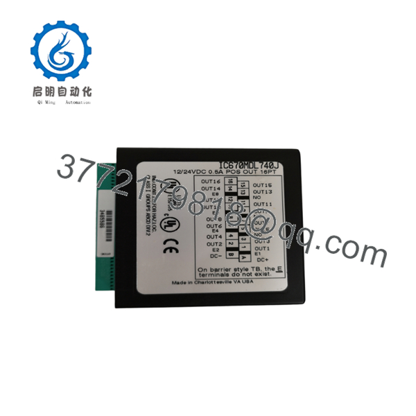
IC670MDL740
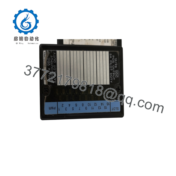
IC670MDL740
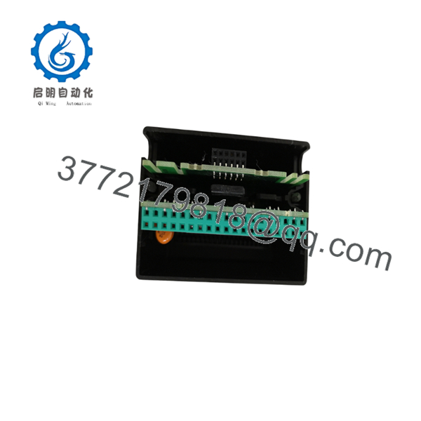
IC670MDL740
Firmware/Software Versions & Upgrade Notes
- BIU Compatibility: The IC670MDL740 operates transparently under all revisions of GE Field Control Bus Interface Units (Genius, Profibus, DeviceNet, or Ethernet BIUs).
- Firmware Dependencies: This discrete I/O module contains no flashable firmware user memory; operating parameters are managed directly by the primary BIU. Ensure your BIU firmware is revision 2.10 or higher for full diagnostic reporting.
- Replacement Risk: Replacing an IC670MDL740 requires no firmware programming or ladder logic modifications. However, if replacing a full I/O node (including the BIU), changing BIU firmware versions mid-swap can break communications with legacy host controllers. Always match the host software hardware configuration files (GSD or EDS files) to the installed BIU revision.
Frequently Asked Questions (FAQ)
Is this unit truly new, or is it a pulled/refurbished part?
This product is a Brand New Surplus unit. It is not used, not pulled from a decommissioned plant, and not refurbished. All modules undergo rigorous quality verification to ensure OEM-level reliability.
Why does buying New Surplus matter compared to lower-cost options on the market?
Refurbished parts frequently hide internal component degradation, such as dried-out electrolytic capacitors or stress-fractured solder joints. A compromised part saving $300 upfront can trigger an emergency shutdown costing tens of thousands of dollars in lost production. New Surplus provides 100% operational life expectancy without the risk of early failure.
What quality control steps are taken before shipping this unit?
Every undergoes inbound anti-counterfeit serial verification, physical inspection of backplane pins, insulation resistance testing, and a live power-on test in a Field Control backplane rig to verify communication and output switching integrity.
Is the GE Fanuc hot-swappable during system operation?
No. Field Control modules do not support live hot-swapping under power. You must remove power from the I/O base before extracting or inserting the to prevent electrical arcing and damage to the backplane communication bus.
Do I need to load software configuration directly onto this module before installation?
No. The is a hardware-configured output card. It receives its bit map and operational state continuously from the node’s Bus Interface Unit (BIU) via the backplane. Simply ensure the physical base keying matches, plug in the module, and connect the field wiring.
What is the warranty coverage on this New Surplus module?
We back this unit with a full 1-year functional warranty. If any operational anomaly occurs under normal operating conditions within 12 months of purchase, we replace the unit immediately from our buffer stock.



