
 WhatsApp: +86 16626708626
 Email:
  Phone: +86 16626708626
Description
Key Technical Specifications
| Parameter | Value |
|---|---|
| Catalog Number | IC693ALG220 |
| Product Family | GE Fanuc Series 90-30 |
| Product Type | Analog voltage input module |
| Number of Channels | 4 |
| Voltage Input Range | −10 to +10 VDC |
| Optional Current Range | −40 to +40 mA with shunt resistor |
| Voltage Resolution | 12-bit binary; 5 mV per LSB |
| Current Resolution | 10-bit standard; up to 11-bit with precision resistor |
| Conversion Speed | 1 ms per channel |
| Update Rate | 4 ms for all four channels |
| Absolute Accuracy | ±10 mV typical; ±30 mV maximum over operating temperature |
| Current Accuracy | ±40 µA typical; ±160 µA maximum over operating temperature |
| Linearity | Less than 1 LSB |
| Input Impedance | Greater than 9 MΩ in voltage mode; 250 Ω in current mode |
| Input Filter Response | 17 Hz |
| Field-to-Logic Isolation | 1,500 VAC |
| Cross-Channel Rejection | Greater than 80 dB |
| Backplane Consumption | 27 mA from +5 VDC bus; 98 mA from isolated +24 VDC bus |
| Calibration | Factory calibrated |
| PLC Data Format | 16-bit two’s-complement format in %AI registers |
The GE Fanuc IC693ALG220 is a four-channel analog input module for Series 90-30 PLC systems. It converts ±10 VDC signals into digital values and can also accept current signals when the specified shunt resistor is installed. Each channel converts in approximately 1 ms, producing a 4 ms update rate for all four channels.
The module provides factory calibration, 12-bit voltage resolution, 17 Hz input filtering, and 1,500 VAC field-to-logic isolation. Verify the exact hardware revision, wiring arrangement, current-input resistor, and PLC configuration before approving it as a replacement.
Troubleshooting Quick Reference
| Symptom | Possible Cause | Relevance to This Part | Quick Check Method | Recommendation |
|---|---|---|---|---|
| Module is not detected by the PLC | Backplane connection, rack power, slot configuration, or failed module | ✅ High | Check Series 90-30 rack power and inspect the module seating; review PLC hardware configuration | Check rack and configuration before replacing the IC693ALG220 |
| All four channels read zero | Missing field supply, incorrect common wiring, or configuration fault | ✅ Medium | Measure the signal between each input terminal and COM with a calibrated multimeter | Verify signal source, common reference, and terminal wiring |
| One channel is always full scale | Open input, incorrect polarity, excessive signal, or failed channel | ✅ High | Measure the voltage directly at the channel and compare it with the PLC’s %AI value | Isolate the field transmitter and test the channel with a known source |
| Reading is approximately half or double the expected value | PLC scaling or two’s-complement interpretation error | ❌ Low | Compare raw %AI data with a known reference voltage and confirm engineering-unit scaling | Correct the PLC scaling before replacing the hardware |
| Input value is noisy | Ground loop, shield problem, unstable transmitter, or poor wiring | ❌ Low | Measure signal stability at the terminal and at the source; inspect shield termination | Repair field wiring and grounding first |
| All channels show the same offset | Common reference error, supply issue, or scaling error | ❌ Low | Apply a known voltage to each channel and compare raw counts | Check COM wiring, transmitter reference, and PLC scaling |
| Current input reads incorrectly | Shunt resistor absent, wrong value, or incorrect input configuration | ✅ High | Confirm the specified precision resistor is installed and measure loop current with a calibrated meter | Do not use the voltage-input wiring assumptions for current operation |
| Input exceeds expected range | Signal above ±10 VDC or noise spikes beyond the allowable input range | ✅ High | Measure peak signal voltage with a multimeter or oscilloscope | Correct the transmitter range and protect the input before continuing |
| Channel response is slow | Normal 17 Hz filtering, source impedance, or external signal conditioning | ❌ Low | Compare the response with a step change and verify the source impedance | Confirm expected filter behavior before replacing the module |
| PLC reports an analog diagnostic fault | Wiring, overrange, rack issue, or module electronics fault | ✅ Medium | Read the PLC fault table and compare diagnostics across all channels | Resolve external faults first; replace only after a known-good signal test fails |
If the fault remains unclear, contact technical support with photos of the module label, rack slot, terminal wiring, measured signal levels, %AI raw values, PLC fault table, and scaling configuration.
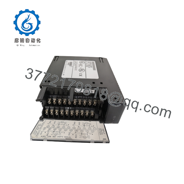
IC693ALG220
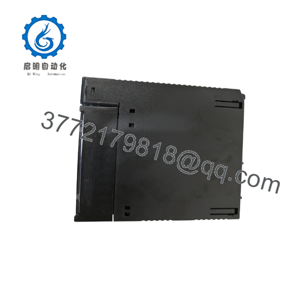
IC693ALG220
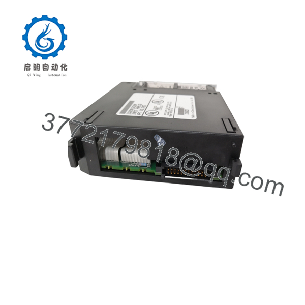
IC693ALG220
Frequently Asked Questions (FAQ)
What signal range does the IC693ALG220 accept?
The standard voltage range is −10 to +10 VDC across four analog input channels. The module can also process −40 to +40 mA signals when the applicable shunt resistor is installed.
Is the IC693ALG220 compatible with the Series 90-30 PLC?
Yes. It is designed for the GE Fanuc Series 90-30 backplane and uses the PLC’s +5 VDC and isolated +24 VDC supplies. Confirm the rack, slot configuration, hardware revision, and PLC programming software before installation.
Can I connect a 4–20 mA transmitter directly?
Do not assume direct compatibility. The current-input function requires the correct shunt resistor and wiring arrangement. Verify the resistor value, terminal connections, and current scaling in the applicable GE Fanuc manual.
What resolution does this module provide?
Voltage conversion uses 12-bit binary resolution, equivalent to 5 mV per LSB over the ±10 V range. Current resolution is lower unless the specified precision resistor is used.
Can I hot-swap the IC693ALG220?
Do not hot-swap it unless the machine documentation specifically authorizes that procedure. Remove power according to the Series 90-30 installation procedure, isolate the field signal, and follow site ESD controls before removing the module.
Will the PLC program remain after replacing the module?
The PLC program normally remains in the CPU, but the replacement must occupy the correct slot and use compatible hardware configuration settings. Confirm channel scaling, signal type, and %AI register mapping before returning the machine to automatic operation.
Why can this module cost less than a factory replacement?
The is a legacy Series 90-30 component commonly sourced through surplus, used, or refurbished inventory. Confirm whether the unit is New Original, New Surplus, or Refurbished (tested), and request the supplier’s test report, warranty, date code, and return terms.



