
 WhatsApp: +86 16626708626
 Email:
  Phone: +86 16626708626
Description
Key Technical Specifications
- Manufacturer: GE Fanuc Automation
- Part Number: IC693ALG221
- Product Family: Series 90-30 PLC
- Module Type: Analog Current Input Module
- Number of Channels: 4 analog current inputs
- Input Signal Range: 4 to 20 mA (default), 0 to 20 mA (jumper selectable)
- Resolution: 12-bit analog conversion
- Conversion Format: 16-bit two’s complement data format
- Input Update Rate: Approximately 2 ms for all four channels
- Calibration: Factory calibrated, 4 µA per count
- Accuracy: ±0.1% full scale at 25 °C
- Input Filter Response: 325 Hz
- Power Consumption: 25 mA from +5 VDC bus, 100 mA from +24 VDC supply
- Configuration: Range selection through I/O terminal board jumpers
- Isolation: External signal isolation from PLC logic through module circuitry
- Connection Type: 20-terminal removable terminal block
The GE Fanuc IC693ALG221 is a four-channel analog current input module for the Series 90-30 PLC platform. It converts industrial current signals into digital values for PLC processing, with selectable 4-20 mA and 0-20 mA input ranges.
Product Introduction
The GE Fanuc IC693ALG221 is a Series 90-30 analog input module designed for current-based process measurement applications. It provides four analog input channels for connecting transmitters, sensors, and instrumentation devices using standard industrial current loops.
The module supports 4-20 mA operation as the default configuration and can be adjusted for 0-20 mA input using hardware jumpers. It is commonly used in legacy GE Fanuc PLC installations where maintaining existing Series 90-30 I/O architecture is required.
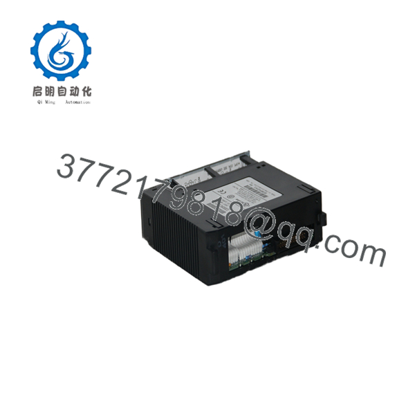
IC693ALG221
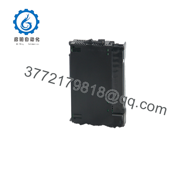
IC693ALG221
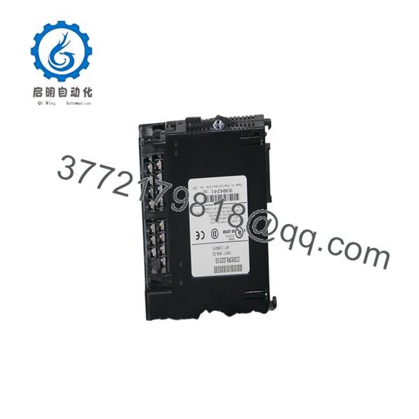
IC693ALG221
Installation & Configuration Guide
Stage 1: Pre-Installation Preparation (Approx. 10 minutes)
⚠️ Safety First
- Notify operations personnel before replacing the analog input module.
- Place the controlled process into a safe condition.
- Apply lockout/tagout procedures before removing the PLC rack power.
- Verify external transmitter loop power is isolated.
Tools Required
- ESD wrist strap
- PH1 screwdriver
- Digital multimeter
- Wire labels
- Smartphone/camera for wiring records
Data Backup
Before removal:
- Record PLC rack slot location.
- Photograph terminal wiring.
- Document each analog channel assignment.
- Record input scaling values in the PLC program.
- Confirm jumper configuration on the existing module.
Stage 2: Removing the Old Module (Approx. 10 minutes)
Steps:
- Shut down PLC rack power.
- Remove the module retaining latch.
- Disconnect the removable terminal block carefully.
- Label each current input channel.
- Pull the module straight out of the Series 90-30 rack.
⚠️ Note:
Keep the original IC693ALG221 available until all analog channels are verified after replacement.
Stage 3: Installing the New Module (Approx. 15 minutes)
Steps:
- Wear an ESD wrist strap before handling the module.
- Verify the replacement part number: IC693ALG221.
- Confirm jumper settings match the removed module.
- Insert the module into the correct Series 90-30 rack slot.
- Reinstall the terminal block.
- Verify current loop polarity and wiring.
Configuration Clone Checklist
- Correct rack slot confirmed
- 4-20 mA / 0-20 mA range verified
- Channel assignments matched
- Scaling parameters copied
- Shield grounding checked
Stage 4: Power-On & Testing (Approx. 20 minutes)
Pre-Power Check
- Confirm no short circuits on input wiring.
- Verify transmitter loop current.
- Check terminal connections.
Power-On Steps
- Restore PLC rack power.
- Check module status indicators.
- Verify the CPU recognizes the analog input module.
- Monitor PLC analog registers.
- Compare displayed values with field transmitter readings.
- Test each channel using a calibrated current source if available.
⚠️ Troubleshooting Note
If readings are incorrect:
- Confirm jumper-selected input range.
- Check transmitter output current.
- Verify PLC scaling logic.
- Inspect shield grounding.
- Confirm terminal wiring.
Frequently Asked Questions (FAQ)
Q1: Is the GE Fanuc IC693ALG221 obsolete?
Yes. The is a legacy Series 90-30 PLC analog input module. Plants still operating Series 90-30 systems commonly source replacement units through surplus and tested inventory channels.
Q2: How many analog inputs does the provide?
The module provides four analog current input channels. Each channel converts current signals into digital values for the PLC CPU.
Q3: Does the support standard 4-20 mA transmitters?
Yes. The default input range is 4-20 mA. The module can also be configured for 0-20 mA operation through jumper selection.
Q4: Can I replace the without changing the PLC program?
Usually yes, if the replacement module is installed in the same rack slot and uses the same channel configuration. Verify scaling, channel assignments, and hardware settings before returning the system to production.
Q5: Can the be hot-swapped?
No. The Series 90-30 analog input module should be replaced with rack power removed. Installing or removing the module under power can damage the module or create PLC faults.
Q6: What are common causes of signal problems?
Common causes include:
- Incorrect 4-20 mA / 0-20 mA jumper setting
- Reversed current loop wiring
- Poor shield grounding
- Incorrect PLC scaling values
- Faulty field transmitter
Q7: What should be verified before ordering ?
Confirm:
- Exact part number:
- System platform: GE Fanuc Series 90-30
- Input type: Analog Current Input
- Channel count: 4
- Required input range: 4-20 mA or 0-20 mA
- Required condition: New Original, New Surplus, or Tested Refurbished
For legacy Series 90-30 systems, the physical module match is only the first step. Always verify configuration data and field wiring before installation.



