
 WhatsApp: +86 16626708626
 Email:
  Phone: +86 16626708626
Description
Key Technical Specifications
| Parameter | Value |
|---|---|
| Catalog Number | IC693ALG390 |
| Product Family | GE Fanuc Series 90-30 |
| Product Type | Analog voltage output module |
| Number of Channels | 2 |
| Output Range | −10 to +10 VDC |
| Resolution | 12-bit binary plus sign; 13-bit effective resolution |
| Resolution per Count | 2.5 mV |
| Update Rate | Approximately 5 ms for both channels |
| Absolute Accuracy | ±5 mV at 25 °C |
| Maximum Offset | 1 mV |
| Maximum Output Load | 5 mA per channel |
| Minimum Load Resistance | 2 kΩ |
| Maximum Load Capacitance | 2,000 pF |
| Nominal Isolated Supply | +24 VDC from the backplane or user supply |
| External Supply Range | 18–30 VDC |
| External Supply Ripple | 10% maximum |
| Field-to-Logic Isolation | 1,500 VAC |
| Backplane Consumption | 32 mA from +5 VDC; 120 mA from isolated +24 VDC |
| PLC Data Format | 16-bit two’s-complement data in %AQ registers |
| Calibration | Factory calibrated |
The GE Fanuc IC693ALG390 is a two-channel analog voltage output module for Series 90-30 PLC systems. It converts %AQ digital data into −10 to +10 VDC control signals for drives, valve positioners, controllers, and other analog field devices. Both channels update in approximately 5 ms.
The module provides 2.5 mV resolution, a 5 mA maximum output load per channel, and 1,500 VAC field-to-logic isolation. Confirm the required isolated +24 VDC supply, output load resistance, terminal wiring, and PLC scaling before installing a replacement.
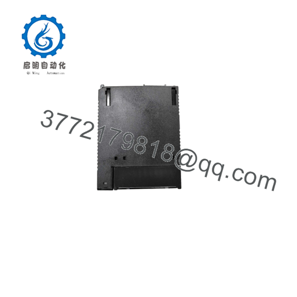
IC693ALG390
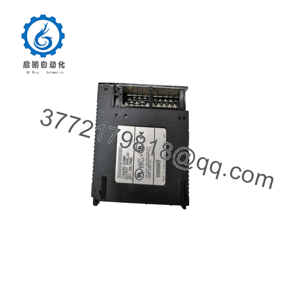
IC693ALG390
Troubleshooting Quick Reference
| Symptom | Possible Cause | Relevance to This Part | Quick Check Method | Recommendation |
|---|---|---|---|---|
| Module is not detected by the PLC | Backplane connection, rack power, slot configuration, or failed module | ✅ High | Check Series 90-30 rack power, module seating, and hardware configuration | Inspect the rack and configuration before replacing the IC693ALG390 |
| Both outputs remain at zero | Missing isolated +24 VDC supply, disabled logic, or incorrect %AQ command | ✅ High | Measure +24 VDC at the module supply terminals and monitor the raw %AQ registers | Check supply and PLC command data before condemning the module |
| One output remains at zero | Open output circuit, wiring fault, failed channel, or incorrect register mapping | ✅ High | Command a known %AQ value and measure DC voltage directly at the output terminal | Test the channel with a high-impedance meter and known PLC command |
| Output is stuck near +10 VDC or −10 VDC | Incorrect scaling, saturated command, or failed output amplifier | ✅ High | Write several known %AQ test values and measure the output at each step | Verify scaling first; replace the module only if the output remains fixed |
| Output is consistently offset | Calibration drift, incorrect scaling, or external load effect | ✅ Medium | Apply zero and midscale commands, then compare measured voltage with expected values | Correct PLC scaling and verify load resistance before replacing the module |
| Output collapses when connected to the field device | Load below 2 kΩ, excessive current demand, or short circuit | ✅ High | Measure load resistance with power isolated; compare output voltage unloaded and loaded | Repair or replace the field device and keep the load within the 5 mA limit |
| Output is unstable | Ground loop, noisy supply, excessive capacitance, or poor shielding | ❌ Low | Measure supply ripple and output stability with the field cable disconnected | Correct grounding, shielding, and supply quality before replacing the module |
| Both channels show the same error | Shared supply, common scaling issue, or backplane problem | ❌ Low | Test both channels with the same known command and inspect isolated +24 VDC | Investigate common power and PLC data before replacing hardware |
| Output updates slowly | Normal PLC scan behavior, program logic, or external filtering | ❌ Low | Trend the %AQ command and measure the output response to a step change | Confirm the application scan time; the module update rate is approximately 5 ms |
| Field actuator moves in the wrong direction | Reversed actuator logic, incorrect scaling, or output wiring polarity | ❌ Low | Compare commanded voltage, terminal polarity, and actuator direction | Correct the application scaling or wiring; do not assume module failure |
If the fault remains unclear, contact technical support with photos of the module label, terminal wiring, measured output voltages, %AQ values, rack status, PLC fault table, and field-device load measurements.
Frequently Asked Questions (FAQ)
What output signal does the IC693ALG390 provide?
The IC693ALG390 provides two analog voltage outputs, each ranging from −10 to +10 VDC. It is not a current-output module; use the correct GE Fanuc analog output model if the application requires 4–20 mA.
What is the maximum load for each output?
Each channel can drive up to 5 mA, which corresponds to a minimum load resistance of approximately 2 kΩ. Loads below that resistance can cause voltage sag, output heating, or inaccurate control.
Does the module require an external 24 VDC supply?
The module normally uses isolated +24 VDC from the Series 90-30 backplane. It also provides terminals for a user-supplied source, which must remain within the 18–30 VDC range and the specified ripple limit.
Can I connect a 4–20 mA actuator to this module?
No. The IC693ALG390 produces voltage, not current. A current-output module such as the appropriate Series 90-30 analog current-output model is required for a 4–20 mA actuator or valve positioner.
How is the analog value scaled in the PLC?
The PLC sends the output command through %AQ registers using a 16-bit two’s-complement format. Verify the configured engineering-unit scaling and test zero, midscale, and full-scale commands before connecting the actuator.
Can I hot-swap the ?
Do not hot-swap it unless the machine documentation explicitly authorizes the procedure. Remove power according to the Series 90-30 installation procedure, isolate the analog field circuit, and observe ESD precautions.
Why can this module cost less than a factory replacement?
The is a mature Series 90-30 component commonly sourced through surplus, used, or refurbished inventory. Confirm the exact condition, hardware revision, test report, warranty, terminal hardware, and return policy before purchase.



