
 WhatsApp: +86 16626708626
 Email:
  Phone: +86 16626708626
Description
Key Technical Specifications
| Parameter | IC693CPU351 Specification |
|---|---|
| Manufacturer | GE Fanuc Automation |
| Part Number | IC693CPU351 |
| Product Family | Series 90-30 |
| Module Type | Single-slot modular CPU |
| CPU Model | CPU 351 |
| Processor | Intel 80386EX |
| Processor Speed | 25 MHz |
| User Program Memory | 240 KB maximum with Release 9.0+ firmware |
| Earlier Firmware Memory | 80 KB |
| Discrete Inputs (%I) | 2,048 |
| Discrete Outputs (%Q) | 2,048 |
| Discrete Global Memory (%G) | 1,280 bits |
| Internal Coils (%M) | 4,096 bits |
| Temporary Coils (%T) | 256 bits |
| Typical Scan Rate | 0.22 ms per 1K Boolean logic |
| Baseplates per System | 8 total |
| Expansion/Remote Baseplates | Up to 7 |
| Backplane Supply | 5 VDC |
| Current Requirement | 890 mA |
| Operating Temperature | 0 to 60 °C (32 to 140 °F) |
| CPU Ports | Port 1 RS-232; Port 2 RS-485 |
| Communication | SNP/SNPX; RTU functions depending on port/configuration |
| Ethernet | Not built into the CPU |
| Key Switch | Yes |
GE Fanuc documentation identifies the IC693CPU351 as a 25 MHz, 80386EX-based single-slot CPU with an 890 mA 5 VDC power requirement and support for up to eight baseplates.
A particularly important procurement detail is firmware revision: Release 9.0 and later supports a maximum 240 KB user program memory, while earlier versions use 80 KB.
Product Introduction
The GE Fanuc IC693CPU351 is a high-performance modular CPU for the Series 90-30 PLC platform. It uses an 80386EX processor running at 25 MHz and is installed in a single CPU slot on the Series 90-30 CPU baseplate. The controller is intended for applications requiring more processing capacity and memory than the earlier Series 90-30 CPU models.
The CPU supports up to 2,048 discrete inputs and 2,048 discrete outputs, with a typical execution rate of approximately 0.22 ms per 1,000 Boolean instructions. It can operate with a total of eight baseplates, consisting of the CPU baseplate plus up to seven expansion and/or remote baseplates.
The IC693CPU351 does not have an integrated Ethernet interface. Network connectivity can instead be provided through compatible Series 90-30 communication modules. Its built-in serial interfaces support legacy GE Fanuc communication functions, making the CPU suitable for maintaining older PLC installations where the existing communication architecture must be preserved.
Important Procurement Point
Do not treat every IC693CPU351 revision as identical for a replacement project. Firmware history matters. GE Fanuc’s release documentation also notes that upgrading CPU firmware can clear the user program, configuration, CPU ID, and status tables, requiring these items to be restored afterward.
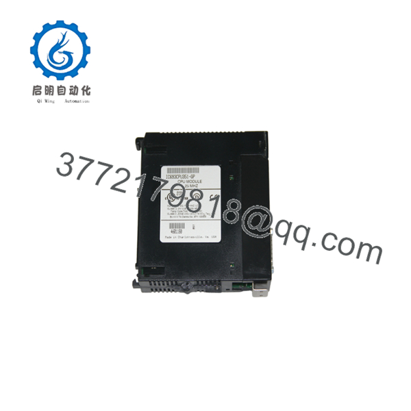
IC693CPU351
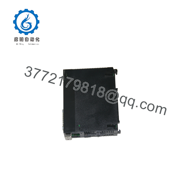
IC693CPU351
Installation & Configuration Guide
Stage 1: Pre-Installation Preparation
⚠️ Safety First
- Place the controlled process in a safe operating condition.
- Apply the plant’s lockout/tagout procedure.
- Remove PLC power before removing the CPU.
- Do not disconnect the CPU while the rack is energized.
Before Removing the Existing CPU:
- Upload and save the PLC application program.
- Record the exact CPU catalog number and hardware revision.
- Record the firmware revision.
- Save the hardware configuration.
- Record SNP/SNPX communication parameters.
- Document CPU key-switch position.
- Photograph the existing rack arrangement.
The firmware revision should be recorded before replacement because available program memory and compatibility can vary by firmware release.
Stage 2: Removing the Existing CPU
Steps:
- Place the PLC in a safe operating state.
- Remove power from the Series 90-30 rack.
- Disconnect serial communication cables.
- Record the key-switch position.
- Release the CPU retaining mechanism.
- Carefully remove the CPU from its single-slot position.
- Inspect the backplane connector for contamination or physical damage.
⚠️ Do not use the replacement CPU to determine the old configuration after removal. Record the original configuration first.
Stage 3: Installing
Steps:
- Wear appropriate ESD protection.
- Verify the replacement is .
- Check the hardware revision and firmware information.
- Insert the CPU into the correct CPU slot.
- Reconnect the serial communication cables.
- Confirm the CPU key switch is in the required position.
- Restore rack power only after the installation inspection is complete.
Configuration Checklist
- CPU catalog number verified
- Hardware revision documented
- Firmware revision checked
- PLC program backup available
- CPU slot confirmed
- Serial communication settings recorded
- Key-switch position verified
- Expansion/remote rack configuration preserved
Stage 4: Power-On & Commissioning
Pre-Power Check
- Verify correct Series 90-30 power supply.
- Confirm CPU is fully seated.
- Check serial cable connections.
- Confirm no loose conductors are present around the rack.
Commissioning Steps
- Apply PLC power.
- Check CPU diagnostic LEDs.
- Connect the programming/configuration software.
- Verify CPU identification and firmware.
- Restore the application program if required.
- Verify hardware configuration.
- Confirm I/O modules are recognized.
- Test serial communications.
- Place the CPU into RUN mode.
- Test representative machine sequences.
Troubleshooting
CPU does not enter RUN:
- Check CPU fault information.
- Verify application program.
- Check hardware configuration.
- Confirm I/O module compatibility.
- Verify power supply voltage.
Communication does not work:
- Confirm RS-232/RS-485 port selection.
- Check SNP/SNPX or RTU configuration.
- Verify baud rate and station parameters.
- Check cable wiring.
- Compare communication settings with the original CPU.
Frequently Asked Questions
Q1: What is the ?
The is a single-slot modular CPU for the GE Fanuc Series 90-30 PLC. It uses a 25 MHz 80386EX processor and supports large discrete and analog memory configurations compared with earlier Series 90-30 CPUs.
Q2: How much memory does the have?
With firmware Release 9.0 or later, the CPU supports up to 240 KB of user program memory. CPUs running firmware before Release 9.0 have a fixed 80 KB user-program memory size.
Q3: Does have Ethernet built in?
No. The CPU does not contain an integrated Ethernet port. Ethernet functionality requires an appropriate Series 90-30 communication module.
Q4: How many expansion racks can support?
The Series 90-30 system can contain up to eight baseplates total: the CPU baseplate plus up to seven expansion and/or remote baseplates.
Q5: What serial interfaces are available?
The CPU has Port 1 RS-232 and Port 2 RS-485 interfaces. The system also provides a serial connection through the PLC power-supply interface for supported SNP/SNPX slave functions.
Q6: Can I replace an with any CPU351 revision?
Do not assume so. Verify the complete catalog number, hardware revision, firmware revision, installed I/O configuration, and communication requirements. GE Fanuc released multiple CPU351 hardware and firmware revisions over the product’s life.
Q7: What happens to the PLC program when replacing the CPU?
The application program must be backed up before replacement. Firmware changes can also clear the user program, configuration, CPU ID, and status tables, so these should be preserved before performing firmware-related work.
Q8: What should I verify before ordering ?
Verify these items against the installed controller:
- Exact part number:
- Hardware revision
- Firmware revision
- User memory requirement
- CPU baseplate compatibility
- I/O configuration
- Expansion/remote rack count
- Serial communication requirements
- Required condition: New Original, New Surplus, Tested Used, or Refurbished
For a legacy Series 90-30 replacement, firmware and revision matching should be treated as part of the part-number verification process, not as a commissioning detail.



