
 WhatsApp: +86 16626708626
 Email:
  Phone: +86 16626708626
Description
Key Technical Specifications
| Parameter | Value |
|---|---|
| Manufacturer | GE Fanuc Automation |
| Model Number | IC693CPU364 |
| Product Series | Series 90-30 |
| Module Type | Single-slot CPU Processor Module |
| Processor Type | Intel 80386EX |
| Processor Speed | 25 MHz |
| User Memory | 240 KB total |
| Typical Scan Rate | 0.22 ms per 1K Boolean logic |
| Ethernet Interface | Built-in Ethernet Interface |
| Ethernet Port Type | 10BASE-T / AAUI interface |
| Supported Baseplates | 8 total (1 CPU baseplate + 7 expansion/remote) |
| Power Consumption | 1.51 A from +5 VDC supply |
| Discrete Inputs | Up to 2,048 points |
| Discrete Outputs | Up to 2,048 points |
| Operating Temperature | 0 to 60 °C (32 to 140 °F) |
| Memory Type | Flash firmware |
| Communication Protocols | Ethernet, SNP/SNP-X, CCM, RTU support |
| Weight | Approx. 2 kg |
Technical specifications are based on GE Fanuc Series 90-30 CPU364 documentation and product references.
Product Introduction
The GE Fanuc IC693CPU364 is a Series 90-30 PLC CPU module with an integrated Ethernet interface. It combines PLC processing and Ethernet communication in a single-slot controller, reducing the need for a separate communication module in existing Series 90-30 installations.
The CPU364 uses a 25 MHz 80386EX processor, provides 240 KB user memory, and supports Ethernet communications through built-in 10BASE-T and AAUI connections. It remains widely used for maintaining legacy machine controls, process skids, and automation systems where full platform migration is not yet practical.
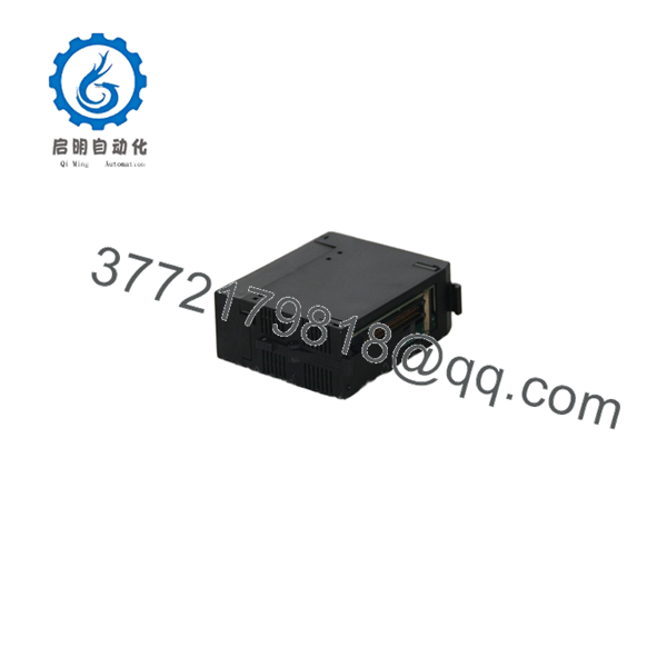
IC693CPU364
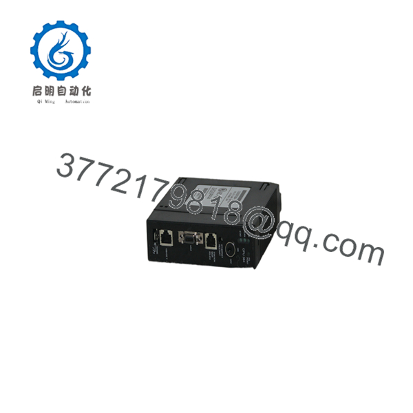
IC693CPU364
Installation & Configuration Guide
Stage 1: Pre-Installation Preparation (Estimated Time: 10 Minutes)
⚠️ Safety First
- Notify operations personnel before starting replacement work.
- Verify the controlled process is in a safe shutdown condition.
- Apply lockout/tagout procedures before removing power.
- Wait at least 5 minutes for capacitor discharge before touching the rack.
Tools Required
- ESD wrist strap
- PH1 screwdriver
- Digital multimeter
- Wire labels
- Smartphone or camera for configuration photos
Data Backup
Before removing the existing CPU:
- Export the PLC program using compatible programming software.
- Record current PLC configuration settings.
- Document Ethernet IP address and communication settings.
- Photograph:
- CPU front panel indicators
- DIP switch positions
- Rack layout
- Wiring arrangement
⚠️ Do not remove the old CPU until configuration records are complete.
Stage 2: Removing the Old Module (Estimated Time: 5 Minutes)
- Remove the CPU front cover or protective bezel.
- Label all connected cables before removal.
- Disconnect communication cables carefully.
- Release rack locking tabs.
- Pull the CPU module straight outward.
⚠️ Do not twist the module during removal. Bent backplane pins can create intermittent faults that are difficult to diagnose.
Inspect:
- Backplane connector condition
- Dust contamination
- Mechanical damage
- Loose terminal connections
Keep the removed CPU available for reference until the replacement is fully commissioned.
Stage 3: Installing the New Module (Estimated Time: 10 Minutes)
- Wear an ESD wrist strap before handling the replacement CPU.
- Verify the replacement label matches:
GE Fanuc IC693CPU364
- Compare firmware revision information with the removed unit.
- Replicate all hardware configuration settings.
- Insert the CPU into the rack slot.
- Press firmly until the module locking mechanism engages.
- Reconnect communication cables.
Configuration Clone Checklist
- CPU model matches
- Firmware revision verified
- DIP settings matched
- Ethernet configuration documented
- Module fully seated
- Locking tabs secured
⚠️ The most common replacement mistake is assuming the replacement CPU has identical firmware and communication settings. Always verify before power-up.
Stage 4: Power-On & Testing (Estimated Time: 15 Minutes)
Pre-Power Check
- Use a multimeter to check the +5 VDC supply rail.
- Verify no short circuit exists on the rack power supply.
- Confirm grounding connection.
Power-On Steps
- Power up the PLC rack only.
- Observe CPU LED indicators.
- Confirm normal RUN status.
- Connect programming software.
- Verify:
- CPU identification
- Firmware revision
- Ethernet settings
- Memory configuration
- Download the saved application program if required.
- Perform I/O simulation testing.
⚠️ Troubleshooting Notes
- Solid fault LED: Check firmware compatibility and memory configuration.
- Ethernet communication failure: Verify IP address, subnet mask, and network switch settings.
- Unexpected PLC stop: Confirm application program compatibility.
Common Replacement Pitfalls From Field Experience
❗ Firmware Revision Mismatch
A replacement CPU may look identical but behave differently.
I have seen Series 90-30 systems fail communication tests after a CPU swap because firmware versions changed between revisions. A small firmware difference can affect Ethernet functions and programming compatibility.
Avoidance:
- Record existing firmware before removal.
- Match replacement firmware whenever possible.
- Keep a backup of the original PLC project.
❗ DIP Switch and Hardware Configuration Errors
Technicians often focus on software and overlook physical settings.
Take a photo before removing the old CPU. This simple step prevents hours of troubleshooting.
❗ Power Supply Loading Issues
Calculate total rack power consumption before adding or replacing modules.
The IC693CPU364 requires approximately 1.51 A from the +5 VDC supply. A power supply operating near its limit may cause unstable PLC behavior.
❗ Ethernet Configuration Loss
The embedded Ethernet interface requires correct network configuration.
Record:
- IP address
- Subnet mask
- Gateway settings
- Ethernet device name
Do not assume the replacement CPU contains the previous network settings.
❗ ESD Damage
Wear a grounded wrist strap and work on an ESD-safe surface.
A static discharge event can damage CPU electronics before the module is installed. The failure may not appear until power-up.
Keep these checks in mind and you’ll save yourself most of the typical rework time during legacy PLC CPU replacement.
Frequently Asked Questions (FAQ)
Q1: Can the GE Fanuc IC693CPU364 be hot-swapped under power?
No. The IC693CPU364 is not designed for hot replacement in a standard Series 90-30 rack. Remove power before extracting the CPU module. Pulling the CPU under power can damage the backplane or create an uncontrolled PLC state.
Q2: Is the obsolete?
Yes. The GE Fanuc Series 90-30 family is a legacy PLC platform. The is no longer a current production controller, but replacement units remain available through surplus and industrial automation inventory channels.
Q3: Will I lose my PLC program when replacing the CPU?
It depends on the condition of the original CPU and memory configuration. Always upload and save the application program before replacement. Do not rely on the existing CPU retaining data after a hardware failure.
Q4: What is the direct replacement for ?
The correct replacement depends on the application requirements. A Series 90-30 CPU upgrade path may include newer GE/Emerson PLC platforms, but migration requires checking I/O modules, communication networks, and programming compatibility.
Verify the OEM documentation before selecting a replacement.
Q5: Why is the available below original OEM pricing?
Legacy automation components are often sourced from surplus inventory, plant closures, and maintenance stock. Pricing depends on condition:
- New Original / New Surplus: Unused unit stored in controlled inventory.
- Refurbished (tested): Previously installed unit inspected and function tested.
Q6: What testing is performed before shipment?
A professional inspection process should include:
- Incoming inspection and serial verification.
- Visual inspection for corrosion, damage, and modification marks.
- Power-up verification.
- Communication testing through Ethernet interface.
- Functional checks using a compatible Series 90-30 test rack.
- Firmware documentation.
- Final QC report generation.
Test photos, videos, and inspection records should be available upon request.
Q7: Can the communicate with modern Ethernet networks?
The CPU364 uses an embedded Ethernet interface designed for industrial Ethernet communication in Series 90-30 systems. Integration with modern networks may require gateway devices, network segmentation, or protocol conversion depending on the application architecture.



