
 WhatsApp: +86 16626708626
 Email:
  Phone: +86 16626708626
Description
Key Technical Specifications
| Parameter | Value |
|---|---|
| Manufacturer | GE Fanuc Automation |
| Model Number | IC693MDL240 |
| Product Series | Series 90-30 |
| Module Type | Discrete AC Input Module |
| Input Points | 16 points |
| Input Arrangement | 1 group with single common |
| Rated Input Voltage | 120 VAC |
| Input Voltage Range | 0 to 132 VAC |
| Frequency Rating | 50/60 Hz |
| Input Current | 12 mA typical at rated voltage |
| On-State Voltage | 74 to 132 VAC |
| Off-State Voltage | 0 to 20 VAC |
| On-State Current | 6 mA minimum |
| Off-State Current | 2.2 mA maximum |
| Input Response Time | 30 ms maximum ON, 45 ms maximum OFF |
| Field-to-Logic Isolation | 1,500 VAC RMS |
| Backplane Current Consumption | 90 mA from 5 VDC bus |
| Terminal Connection | 20-pin removable terminal block |
| LED Indicators | Individual input status LEDs |
| Installation Location | Any I/O slot in Series 90-30 5-slot or 10-slot baseplate |
| Operating Temperature | 0 to 60 °C (32 to 140 °F) |
The GE Fanuc IC693MDL240 is a Series 90-30 discrete input module providing 16 channels for 120 VAC field signals. It accepts 0 to 132 VAC input signals and draws approximately 90 mA from the PLC backplane 5 VDC supply.
Product Introduction
The GE Fanuc IC693MDL240 is a Series 90-30 PLC digital input module designed to monitor 16 channels of 120 VAC field devices. It is commonly installed in industrial machines, process skids, and legacy control panels using AC-operated pushbuttons, limit switches, proximity devices, and relay contacts.
The module provides individual LED indication for each input point, electrical isolation between field wiring and PLC logic, and direct compatibility with Series 90-30 I/O racks. It remains a practical replacement option for maintaining existing systems where redesigning the control architecture would create unnecessary downtime.
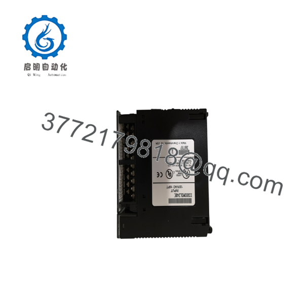
IC693MDL240
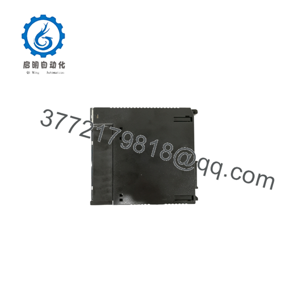
IC693MDL240
Installation & Configuration Guide
Stage 1: Pre-Installation Preparation (Estimated Time: 10 Minutes)
⚠️ Safety First
- Notify operations personnel before starting replacement work.
- Confirm the machine or process is in a safe condition.
- Apply lockout/tagout procedures.
- Remove PLC rack power.
- Wait at least 5 minutes for stored electrical energy discharge.
⚠️ The IC693MDL240 handles 120 VAC field wiring. Verify zero voltage before touching terminals.
Tools Required
- ESD wrist strap
- PH1 screwdriver
- Digital multimeter
- Wire labels
- Smartphone/camera for documentation
Data Backup
Before removing the existing module:
- Save the PLC application program.
- Record the module location in the rack.
- Photograph:
- Terminal wiring
- Module position
- Input labels
- Field device connections
- Verify the replacement part number:
GE Fanuc IC693MDL240
Stage 2: Removing the Old Module (Estimated Time: 5 Minutes)
- Remove the front cover if installed.
- Label every field wire before disconnecting.
- Disconnect the terminal block carefully.
- Release the module locking tabs.
- Pull the module straight outward.
Inspect:
- Backplane connector pins
- Terminal block condition
- Rack slot contacts
- Signs of overheating or corrosion
⚠️ Keep the original module until the replacement has passed functional testing.
Stage 3: Installing the New Module (Estimated Time: 10 Minutes)
- Wear an ESD wrist strap.
- Confirm the replacement module matches:
IC693MDL240 — 120 VAC 16 Point Input Module
- Verify terminal wiring against the original photos.
- Insert the module into the correct Series 90-30 I/O slot.
- Press firmly until fully seated.
- Secure locking tabs.
- Reconnect field wiring.
Configuration Clone Checklist
- Correct module model installed
- Terminal wiring matches original
- Common connection verified
- Module fully seated
- Locking tabs secured
⚠️ Do not connect 24 VDC devices to this module. The is a 120 VAC input module.
Stage 4: Power-On & Testing (Estimated Time: 15 Minutes)
Pre-Power Check
- Verify no wiring shorts exist.
- Check AC input voltage using a multimeter.
- Confirm terminal labeling.
Power-On Steps
- Power up the PLC rack.
- Observe CPU status.
- Check input LEDs.
- Activate field devices one at a time.
- Verify PLC input table status.
- Confirm machine sequence operation.
⚠️ Troubleshooting Notes
- Input LED OFF with voltage present:
- Check common terminal wiring.
- Verify input voltage exceeds ON threshold.
- Multiple inputs unstable:
- Inspect AC supply quality.
- Check field wiring noise.
- PLC does not recognize module:
- Verify rack configuration and PLC hardware setup.
Common Replacement Pitfalls From Field Experience
❗ Wrong Voltage Module Selection
The Series 90-30 family contains many similar-looking I/O modules.
The requires 120 VAC input signals.
I have seen technicians replace a failed AC input card with a 24 VDC model because the front labels looked similar. The PLC powered up, but every field signal failed.
Avoidance:
- Match the complete model number.
- Verify voltage rating before installation.
- Check the wiring diagram.
❗ Terminal Wiring Mistakes
The uses a grouped input arrangement with a common terminal.
A single loose common connection can make all 16 inputs appear failed.
Avoidance:
- Photograph wiring before removal.
- Label each conductor.
- Tighten terminals correctly.
❗ Field Voltage Misdiagnosis
A measured voltage does not always mean the input circuit is working correctly.
The module requires sufficient ON-state voltage.
Specifications:
- ON state: 74 to 132 VAC
- OFF state: 0 to 20 VAC
❗ Backplane Contact Problems
Legacy Series 90-30 systems can develop oxidation on connectors after years of service.
If a replacement module fails immediately:
- Inspect rack contacts.
- Check seating pressure.
- Verify neighboring modules.
❗ ESD Damage
Always use ESD protection.
A static discharge event can damage input circuitry before installation.
Use:
- Grounded wrist strap
- ESD mat
- Anti-static packaging
Keep these checks in mind and you’ll save yourself most of the typical rework time during Series 90-30 I/O replacement.
Frequently Asked Questions (FAQ)
Q1: Can the GE Fanuc be hot-swapped?
No. The is not designed for live removal from a standard Series 90-30 rack. Remove power before replacing the module to protect the backplane and connected field devices.
Q2: Is the obsolete?
Yes. The GE Fanuc Series 90-30 platform is a legacy PLC family. The is no longer a current production module, but replacement inventory remains available through industrial automation suppliers.
Q3: Can the accept 24 VDC inputs?
No.
The is designed for 120 VAC input signals. For 24 VDC sensors or switches, use the appropriate Series 90-30 DC input module.
Q4: How many input channels does the provide?
The module provides:
- 16 discrete AC input points
- One common input group
- Individual LED status indication
Q5: Will replacing the affect my PLC program?
Normally, replacing an identical I/O module does not require program changes. However, always verify the hardware configuration after replacement.
If the slot assignment changes, the PLC configuration may require updating.
Q6: Why is the available below the original OEM price?
Legacy automation components are commonly sourced from:
- Plant spare inventory
- Equipment decommissioning
- Surplus stock
Condition should be clearly identified:
- New Original / New Surplus: Unused module stored in inventory.
- Refurbished (tested): Previously installed module inspected and function tested.
Q7: What testing should be performed before shipment?
A proper inspection process should include:
- Serial number verification.
- Visual inspection for corrosion, damage, and modification marks.
- Power-up test on a genuine Series 90-30 rack.
- Input channel simulation testing.
- LED status verification.
- Electrical parameter checks.
- Final QC report documentation.
Test photos and videos should be available upon request.



