
 WhatsApp: +86 16626708626
 Email:
  Phone: +86 16626708626
Description
Key Technical Specifications
| Parameter | Value |
|---|---|
| Manufacturer | GE Fanuc Automation |
| Model Number | IC693PTM101 |
| Product Series | Series 90-30 |
| Module Type | Power Transducer Module (PTM) |
| Package Components | Processing module, matched interface board, 1 m interface cable |
| Interface Cable | IC693CBL341, 1 m |
| Voltage Measurement | 10–150 VAC RMS |
| Nominal Voltage | 120 VAC |
| Current Measurement | 0–7.5 A RMS |
| Nominal Current | 5 A RMS |
| Frequency Range | 35–70 Hz |
| Measurement Resolution | 14-bit |
| Operating Modes | Power Monitor, Synchro Monitor |
| Data Calculation Rate | 20 ms @ 50 Hz; 16.67 ms @ 60 Hz |
| Backplane Supply | 5 VDC |
| Backplane Current | 400 mA maximum |
| Power Dissipation | 4 W maximum |
| Backplane Isolation | 1,500 V |
| Voltage Input Impedance | >200 kΩ |
| Current Input Impedance | <50 mΩ |
| PLC Data Registers | %I, %Q, %AI, %AQ |
| Compatible PLC | Series 90-30 CPUs |
| Mounting | Series 90-30 baseplate |
| Lifecycle | Discontinued / Obsolete |
The IC693PTM101 is the longer-cable version of GE Fanuc’s Series 90-30 Power Transducer Module. The package contains the processing module, its matched interface board, and a 39-inch (1 m) interface cable. GE’s manual explicitly states that the processing module and interface board are a matched set and should not be separated as individual replacement components.
The PTM accepts voltage and current signals from user-supplied potential transformers (PTs) and current transformers (CTs). It calculates electrical parameters including RMS voltage/current, kW, kVAR, kVA, power factor, frequency, and accumulated energy.
Product Introduction
The GE Fanuc IC693PTM101 is a Series 90-30 Power Transducer Module used for electrical power monitoring and generator-to-grid synchronization applications. It processes voltage and current signals from external PTs and CTs, then transfers calculated measurements into the PLC for reporting, control, load-shedding, and fault-monitoring functions.
The IC693PTM101 supports 10–150 VAC RMS voltage measurement, 0–7.5 A RMS current measurement, and 35–70 Hz operation. Its distinguishing feature versus the IC693PTM100 is the supplied 1 m interface cable, rather than the 0.5 m cable supplied with the PTM100.
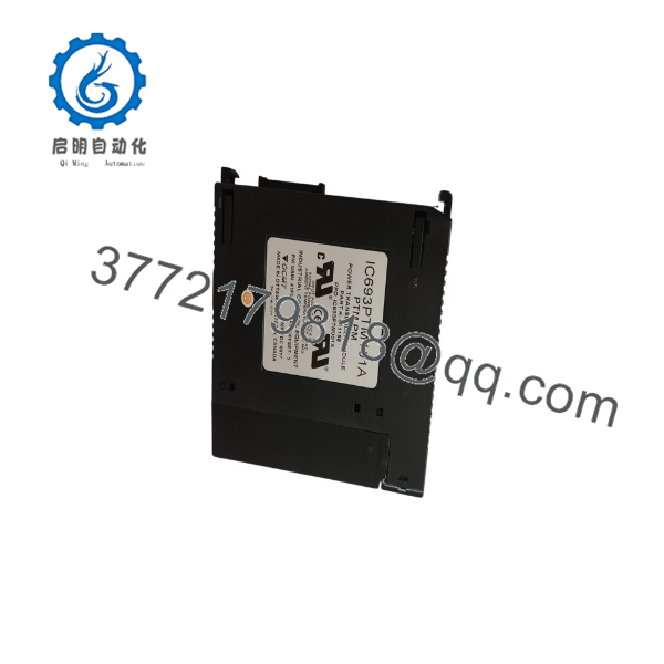
IC693PTM101
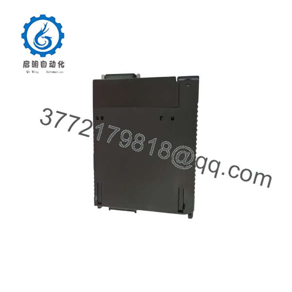
IC693PTM101
Installation & Configuration Guide
Stage 1: Pre-Installation Preparation — About 15 Minutes
⚠️ Safety First
The IC693PTM101 interface board connects to potentially hazardous electrical measurement circuits. GE’s manual specifically warns that the interface board can be connected to hazardous voltages.
- Notify operations and obtain approval for the shutdown.
- Place the generator, switchgear, or monitored equipment in a verified safe state.
- Apply the site’s lockout/tagout procedure.
- Isolate the PT/CT measurement circuits according to the approved electrical procedure.
- Verify absence of hazardous voltage with an appropriately rated meter.
- Allow the equipment to discharge according to the site electrical safety procedure.
⚠️ Do not disconnect PT or CT wiring simply because the PLC rack is powered down. The PTM interface board is connected to external measurement circuits.
Tools Required
- ESD wrist strap
- PH1 screwdriver
- Properly rated digital multimeter
- Approved electrical test equipment
- Wire labels
- Smartphone or camera
- Appropriate insulated tools
- Existing PT/CT wiring drawings
Data Backup
Before removing the existing unit:
- Save the Series 90-30 PLC application.
- Record the PTM rack and slot.
- Photograph the processing module.
- Photograph the interface board.
- Photograph every PT/CT terminal connection.
- Record CT polarity and phase identification.
- Record the existing PT ratios and CT ratios.
- Record the PTM operating mode.
- Document any PLC %I, %Q, %AI, and %AQ registers used by the application.
The PTM transfers its measurements through PLC memory, including %I, %Q, %AI, and %AQ data areas.
Stage 2: Removing the Old Module — About 10 Minutes
- Confirm the external measurement circuits are isolated and safe.
- Photograph the complete installation before disconnecting anything.
- Label all PT and CT conductors.
- Label the interface cable at both ends.
- Disconnect the interface cable.
- Disconnect the field wiring from the interface board using the approved electrical procedure.
- Release the Series 90-30 module retention mechanism.
- Remove the processing module straight from the rack.
- Remove the matched interface board if the replacement includes a complete PTM set.
- Inspect the backplane and interface-board terminals.
Look for:
- Heat discoloration
- Loose terminals
- Damaged insulation
- Corrosion
- Bent connector pins
- Damaged cable connectors
- Evidence of previous wiring modifications
⚠️ Do not discard the original PTM assembly until the replacement has passed electrical measurement and PLC data-validation tests.
Stage 3: Installing the New Module — About 15 Minutes
- Put on an ESD wrist strap.
- Verify the replacement marking:
GE Fanuc IC693PTM101
- Confirm that the package contains the matched processing module, interface board, and 1 m interface cable.
- Verify the PT and CT ranges against the application.
- Install the interface board in the approved panel location.
- Install the processing module into the Series 90-30 rack.
- Secure the module.
- Connect the 1 m interface cable.
- Reconnect the PT and CT circuits according to the original drawings.
- Verify every phase and polarity connection before energization.
Configuration Clone Checklist
- model verified
- Matched interface board verified
- 1 m cable verified
- PT ratio documented
- CT ratio documented
- Phase A/B/C identification verified
- CT polarity verified
- Operating mode verified
- PLC register assignments documented
- Interface cable fully seated
⚠️ Do not substitute the IC693PTM100 cable simply because the processing module appears identical. The PTM100 includes a 0.5 m cable; the PTM101 includes a 1 m cable.
Stage 4: Power-On & Testing — About 20 Minutes
Pre-Power Check
- Verify the PT/CT circuits against the electrical drawings.
- Confirm all terminal screws are properly secured.
- Verify CT polarity.
- Confirm PT secondary voltage is within the PTM measurement range.
- Confirm the measured frequency is within 35–70 Hz.
- Check the interface cable connections.
- Verify the Series 90-30 rack power supply capacity.
Power-On Steps
- Power the Series 90-30 rack.
- Confirm the CPU reaches its normal operating state.
- Verify the PTM module status.
- Confirm valid voltage measurements.
- Confirm valid current measurements.
- Check the PLC data registers.
- Compare PTM readings against an independent calibrated meter.
- Verify phase relationships.
- Check calculated kW, kVAR, kVA, and power factor.
- For synchronization applications, verify generator/grid voltage and phase measurements before enabling automatic control.
The PTM calculates data at 20 ms at 50 Hz and 16.67 ms at 60 Hz. GE documentation also describes measurement and diagnostic data transferred into PLC memory for application processing.
⚠️ Troubleshooting Notes
- No voltage measurement: Check PT secondary wiring, fuse status, phase identification, and interface-board connections.
- No current measurement: Check CT wiring and polarity.
- Incorrect power factor: Check phase-to-CT correspondence and CT polarity.
- Voltage readings correct but kW is wrong: Suspect phase/CT association or ratio configuration.
- PLC receives no PTM data: Check rack seating, PTM configuration, and PLC data mapping.
- Different readings from the old unit: Compare CT/PT ratios and phase assignments before replacing additional hardware.
Frequently Asked Questions (FAQ)
Q1: What is the used for?
The is an intelligent power measurement and monitoring module for the GE Fanuc Series 90-30 PLC. It measures electrical voltage and current through external PTs and CTs and calculates parameters such as real power, reactive power, apparent power, energy, frequency, and power factor.
It can be used for power monitoring, reporting, load shedding, fault monitoring, and generator/grid synchronization applications.
Q2: What is the difference between IC693PTM100 and ?
The primary difference is the supplied interface cable length.
- IC693PTM100: 0.5 m cable
- 1 m cable
GE’s documentation states that the processing module and interface board are matched components, while the two cable lengths are separately cataloged as IC693CBL340 and IC693CBL341.
Q3: What voltage and current can the measure?
The documented measurement range is approximately 10–150 VAC RMS for voltage and 0–7.5 A RMS for current, with a nominal current range of 5 A RMS. The operating frequency range is 35–70 Hz.
The PTM is intended to work with external PTs and CTs. Do not connect primary generator or utility voltage directly to the module.
Q4: Can the be hot-swapped?
No. Treat the processing module as a power-off replacement, and more importantly, treat the interface-board wiring as a potentially hazardous electrical circuit.
The Series 90-30 rack can be powered down for the module replacement, but the PT/CT circuits require their own electrical isolation procedure. GE explicitly warns about hazardous voltage at the PTM interface board.
Q5: Is obsolete?
Yes. The is a discontinued legacy Series 90-30 product. Current industrial automation suppliers list it as obsolete while continuing to offer new-surplus and refurbished inventory.
For a production spare, request the exact processing-module revision, interface-board revision, cable length, condition, test report, and warranty. Do not purchase based only on the catalog number.
Q6: Does include the interface board and cable?
Yes. The catalog configuration includes the processing module, matched interface board, and 1 m interface cable. The IC693PTM100 uses the same general PTM architecture but includes a 0.5 m cable.
This matters when comparing surplus listings. A listing for only the processing module is not equivalent to a complete package.
Q7: Can the be used for protective relay or billing applications?
No. GE’s catalog specifically states that the PTM is intended for power measurement and monitoring and is not intended to provide a protective relay function or to be used for energy billing purposes.
For protection or revenue metering, use equipment specifically certified and designed for those functions.



