
 WhatsApp: +86 16626708626
 Email:
  Phone: +86 16626708626
Description
3. Key Technical Specifications
| Parameter | Value |
|---|---|
| Nominal Input Voltage | 24 or 48 VDC |
| Input Voltage Range (Start) | 21 to 56 VDC |
| Input Voltage Range (Run) | 18 to 56 VDC |
| Input Power | 50 W maximum at full load |
| Inrush Current | 4 A peak, 100 ms maximum |
| Total Output Power | 30 W maximum (all outputs combined) |
| +5 VDC Output | 15 W maximum (5.0–5.2 V, 5.1 V nominal) |
| +24 VDC Relay Output | 15 W maximum (24–28 V) |
| +24 VDC Isolated Output | 20 W maximum (21.5–28 V) |
| Overvoltage Protection (+5 V) | 6.4 to 7 V |
| Overcurrent Protection (+5 V) | 4 A maximum |
| Hold-up Time | 14 ms minimum |
| Status LEDs | PWR, OK, RUN, BATT |
| Serial Port | RS-485 (9-pin D-shell) for programmer / HHP |
| Mounting Location | Leftmost slot of any Series 90-30 baseplate |
4. Product Introduction
The GE Fanuc IC693PWR322F is a 30-watt standard power supply for the Series 90-30 PLC. It accepts a wide-range 24/48 VDC input (18–56 VDC running) and supplies three regulated outputs: +5 VDC for the backplane, +24 VDC Relay for relay-output modules, and +24 VDC Isolated for field devices and certain I/O modules. Total combined output power must not exceed 30 W.
The module installs in the leftmost slot of any 5- or 10-slot baseplate and includes status LEDs plus an RS-485 serial port for programming devices. It will not start below 21 VDC but will continue to operate down to 18 VDC once running. The F revision is functionally identical to later revisions of the IC693PWR322 and remains a direct replacement for existing DC-powered Series 90-30 systems.
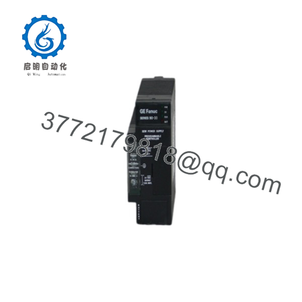
IC693PWR322F
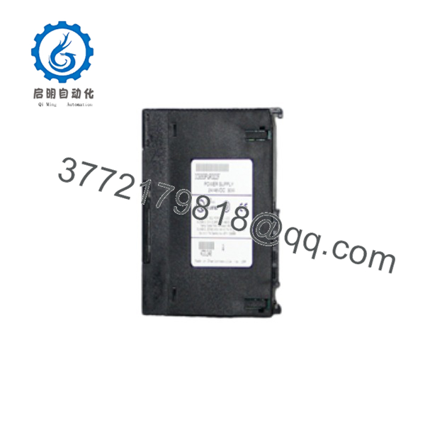
IC693PWR322F
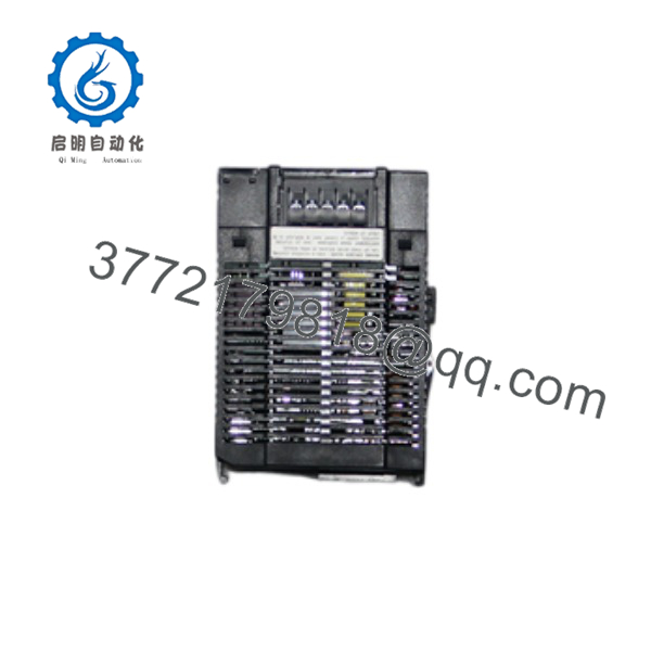
IC693PWR322F
5. Troubleshooting Quick Reference
| Symptom | Possible Cause | Relevance to this Part | Quick Check Method | Recommendation |
|---|---|---|---|---|
| PWR LED off, no outputs | Input voltage too low or reverse polarity | ✅ High | Measure DC input at terminals; confirm ≥21 V for start, polarity correct | Raise input voltage or correct wiring |
| OK LED off / system faulted | Overload, short, or internal fault | ✅ High | Measure +5 V, +24 V Relay, and Isolated rails under load | Remove modules one at a time to isolate overload |
| RUN LED off while CPU tries to run | Insufficient +5 V or hold-up problem | ✅ Medium | Scope +5 V rail during power-up and under load | Verify total load ≤30 W; check for intermittent input dips |
| BATT LED on | Low or missing backup battery | ❌ Low (CPU battery) | Check CPU battery voltage | Replace CPU battery (IC693ACC301); not a power-supply fault |
| Outputs drop under load | Exceeding 15 W / 20 W / 30 W limits | ✅ High | Calculate total module current draw on each rail | Reduce load or upgrade to higher-capacity supply (e.g., PWR331) |
| Will not start but runs once powered | Input voltage between 18–21 VDC | ✅ Medium | Measure input at the moment of power application | Ensure input is ≥21 VDC at start-up |
If the supply continues to fault after these checks, photograph the LED faceplate, measure all three output rails, and capture the PLC fault table before contacting technical support.
6. Frequently Asked Questions (FAQ)
Q: What does the “F” suffix mean on IC693PWR322F? A: It identifies the hardware revision (Series F). Functional specifications are identical to other late revisions of the IC693PWR322. Most systems accept any revision from F onward interchangeably.
Q: Is this power supply still manufactured? A: No. The Series 90-30 platform is mature. Available units are New Surplus or tested refurbished stock. Keep spares if the system is expected to remain in service long-term.
Q: What is the difference between PWR322 and the higher-capacity PWR331? A: The PWR322 is rated 30 W total with 15 W on the +5 V rail. The PWR331 provides higher +5 V capacity (30 W class) and is preferred for densely populated racks. Do not substitute without recalculating the load.
Q: Can I use this supply on an AC-powered system? A: No. The IC693PWR322 is DC-input only (24/48 VDC). For AC input use IC693PWR321 or IC693PWR330.
Q: Why won’t it start below 21 V but continues to 18 V once running? A: This is by design. The start-up circuit requires ≥21 VDC; after the supply is running it can ride through down to 18 VDC. Ensure the source can deliver at least 21 V at the moment of power application.
Q: Does it include a battery? A: No. The BATT LED monitors the CPU’s backup battery, not a battery inside the power supply. Replace the CPU battery (IC693ACC301) when the BATT LED is on.
Q: Can this module be hot-swapped? A: No. Power down the entire rack before removing or inserting the power supply. Hot-swapping risks damage to the backplane and all modules.
Q: Why is New Surplus priced lower than original list? A: These are unused original modules from OEM or distributor surplus inventory. Each unit is visually inspected, powered on a genuine Series 90-30 rack, and verified for correct output voltages and LED status before shipment. Test documentation is available on request.



