
 WhatsApp: +86 16626708626
 Email:
  Phone: +86 16626708626
Description
Key Technical Specifications
| Parameter | Value |
|---|---|
| Manufacturer | GE Fanuc |
| Model Number | IC693PWR331 |
| Product Series | Series 90-30 |
| Module Type | High-Capacity Power Supply |
| Nominal Input | 24 VDC |
| Input Voltage Range — Start | 18–30 VDC |
| Input Voltage Range — Run | 12–30 VDC |
| Maximum Input Power | 50 W |
| Total Output Power | 30 W maximum |
| +5 VDC Output | 30 W maximum |
| +24 VDC Isolated Output | 20 W maximum |
| +24 VDC Relay Output | 15 W maximum |
| Combined Output Limit | 30 W maximum |
| +5 VDC Output Voltage | 5.0–5.2 VDC |
| 24 VDC Output Range | 19.2–28.8 VDC |
| Inrush Current | 4 A peak, 100 ms maximum |
| Hold-Up Time | 10 ms minimum |
| 5 VDC Overcurrent Protection | 7 A maximum |
| Status LEDs | PWR, OK, RUN, BATT |
| Serial Port | RS-485 compatible |
| Battery Backup | Lithium battery connection |
| Mounting | Series 90-30 baseplate |
| Lifecycle | Discontinued / Obsolete |
The IC693PWR331 is the 24 VDC-input high-capacity power supply for GE Fanuc Series 90-30 systems. Its total available output power is 30 W, with separate 5 VDC, isolated 24 VDC, and relay 24 VDC outputs. GE’s documentation specifies that the combined output load cannot exceed 30 W.
Product Introduction
The GE Fanuc IC693PWR331 is a Series 90-30 high-capacity power supply designed for PLC racks requiring more 5 VDC capacity than the standard supply. It accepts a nominal 24 VDC input and provides +5 VDC, isolated +24 VDC, and +24 VDC relay power for the control system and compatible I/O modules.
The important specification is the 30 W combined output limit, not the individual maximums printed for each output. The supply can allocate up to 30 W to the 5 VDC output, while the isolated 24 VDC and relay 24 VDC outputs have separate limits.
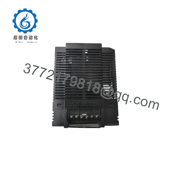
IC693PWR331
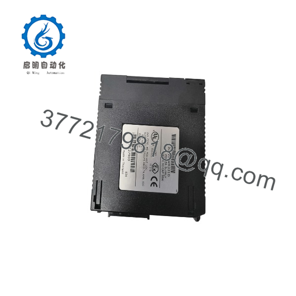
IC693PWR331
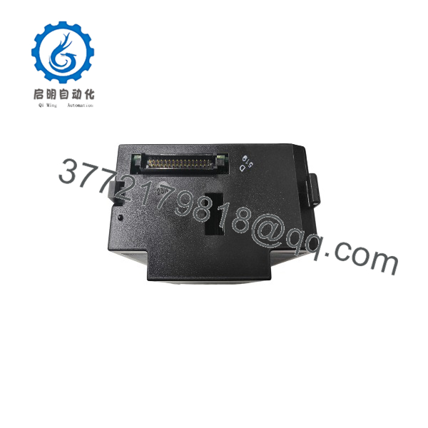
IC693PWR331
Installation & Configuration Guide
Stage 1: Pre-Installation Preparation — About 10 Minutes
⚠️ Safety First
- Notify operations before removing PLC rack power.
- Place the controlled equipment in a verified safe state.
- Apply the site’s lockout/tagout procedure.
- Disconnect the external 24 VDC supply.
- Wait at least 5 minutes for stored energy to discharge.
- Verify the input terminals are de-energized with a properly rated multimeter.
⚠️ Do not assume that shutting down the PLC CPU removes the external 24 VDC supply. Verify the power terminals directly.
Tools Required
- ESD wrist strap
- PH1 screwdriver
- Digital multimeter
- Wire labels
- Smartphone or camera
- Appropriate insulated tools
Data Backup
Before removing the IC693PWR331:
- Save the current Series 90-30 PLC project.
- Record the rack and power-supply position.
- Photograph the power-supply wiring.
- Record the external DC supply voltage.
- Photograph the battery connection.
- Record the CPU and I/O module configuration.
- Check the rack’s total 5 VDC and 24 VDC load.
⚠️ The IC693PWR331 contains the lithium battery connection used for CPU memory backup in applicable Series 90-30 configurations. Do not casually disconnect the battery during a power-supply replacement.
Stage 2: Removing the Old Module — About 5 Minutes
- Confirm the external 24 VDC supply is isolated.
- Verify zero voltage at the power-supply input terminals.
- Photograph the terminal wiring.
- Label the positive and negative conductors.
- Disconnect the external input wiring.
- Release the module retention mechanism.
- Pull the IC693PWR331 straight out of the rack.
- Inspect the backplane connector.
Check for:
- Bent backplane contacts
- Heat discoloration
- Loose terminals
- Corrosion
- Damaged wiring
- Evidence of overheating
⚠️ Keep the original power supply available until the replacement has successfully powered the complete rack.
Stage 3: Installing the New Module — About 10 Minutes
- Put on a grounded ESD wrist strap.
- Verify the replacement marking:
- Confirm the replacement is a 24 VDC-input unit.
- Verify that the rack power budget is within the ‘s limits.
- Insert the module into the Series 90-30 baseplate.
- Seat it firmly against the backplane.
- Lock the module in place.
- Reconnect the 24 VDC input wiring.
- Verify polarity before applying power.
- Check the battery connection.
Configuration Clone Checklist
- model verified
- 24 VDC input verified
- Input polarity verified
- 5 VDC rack load calculated
- Isolated 24 VDC load calculated
- Relay 24 VDC load calculated
- Total output ≤ 30 W
- Battery connection verified
- Terminal screws secured
- Module fully seated
⚠️ Do not size each output independently and then add the maximums together. The combined output cannot exceed 30 W.
Stage 4: Power-On & Testing — About 15 Minutes
Pre-Power Check
- Confirm input polarity.
- Measure the external DC supply.
- Verify the input is within the applicable operating range.
- Check for shorts between positive and negative input.
- Confirm the calculated rack load is within the power-supply capacity.
The can run with an input between 12 and 30 VDC, but GE documentation specifies that it will not initially start when the applied input is below approximately 18 VDC.
Power-On Steps
- Energize the external 24 VDC supply.
- Observe the PWR LED.
- Check the OK and RUN indicators.
- Confirm the PLC CPU starts normally.
- Check the BATT indication.
- Verify the rack’s I/O modules initialize.
- Measure the +5 VDC rail if troubleshooting is required.
- Verify the 24 VDC relay and isolated outputs where applicable.
- Place the PLC into the required operating state.
- Monitor the rack under normal load.
⚠️ Troubleshooting Notes
- No PWR indication: Check the external 24 VDC supply and polarity.
- PWR present but CPU does not start: Check the 5 VDC rail and total rack load.
- 5 VDC low: Check for excessive backplane load or a shorted module.
- Intermittent PLC faults: Check supply voltage stability and rack loading.
- Battery indication abnormal: Inspect battery condition and connection.
- Supply shuts down under load: Calculate the complete rack’s combined power demand.
Common Replacement Pitfalls From Field Experience
❗ 1. Confusing With Another Series 90-30 Supply
The part number matters.
The is specifically the 24 VDC-input high-capacity supply. It is not interchangeable with every Series 90-30 power supply simply because the modules physically resemble one another. GE’s documentation identifies its nominal input as 24 VDC and its usable run range as 12–30 VDC.
Avoidance: Match the complete catalog number before installation.
❗ 2. Adding the Three Output Ratings Incorrectly
This is a classic power-budget mistake.
The module lists:
- +5 VDC: 30 W maximum
- +24 VDC isolated: 20 W maximum
- +24 VDC relay: 15 W maximum
You cannot simply add those figures and claim 65 W of available output.
The combined output limit is 30 W.
Avoidance: Calculate actual simultaneous demand across the entire rack.
❗ 3. Forgetting the High 5 VDC Demand of Legacy Modules
A Series 90-30 rack can contain modules with substantial 5 VDC backplane demand.
This is one reason the exists: it provides substantially more 5 VDC capacity than standard supplies.
Field rule: Add the actual 5 VDC current requirements of every installed module before selecting a replacement power supply.
❗ 4. Assuming 12 VDC Will Always Start the Supply
The specifications can be confusing.
The can operate over a 12–30 VDC run range, but GE specifies a higher minimum for startup. An initial input below approximately 18 VDC may prevent the supply from starting.
If you’re diagnosing a system supplied from a battery bank, measure the voltage at the PWR331 terminals during startup, not only at the battery.
❗ 5. Ignoring the Battery During Replacement
The Series 90-30 power supply includes the battery connection associated with CPU memory backup.
A power-supply replacement is therefore not just a matter of moving three wires. Confirm the PLC’s memory-retention strategy before removing the existing unit.
Avoidance: Back up the PLC program first and follow the applicable Series 90-30 battery procedure.
❗ 6. Using an Undersized External DC Supply
The can deliver up to 30 W of combined output, but its external input is not a trivial load.
At 24 VDC, 50 W represents approximately 2.1 A before accounting for startup conditions and system margin.
Use an appropriately sized external supply and leave engineering margin for voltage drop, temperature, and aging.
❗ 7. Replacing the Supply Without Checking the Rack
If the old supply failed because of an overloaded rack, installing another will not solve the underlying problem.
Check every module.
A shorted I/O module, overloaded relay supply, or excessive 5 VDC backplane demand can bring the replacement supply down again.
Frequently Asked Questions (FAQ)
Q1: What type of power supply is ?
The is a high-capacity 24 VDC-input power supply for the GE Fanuc Series 90-30 PLC. It provides +5 VDC, isolated +24 VDC, and +24 VDC relay power.
Q2: What is the total output power of ?
The total combined output is 30 W maximum.
The individual output limits are:
- +5 VDC: 30 W maximum
- +24 VDC isolated: 20 W maximum
- +24 VDC relay: 15 W maximum
Those individual figures do not add together. The combined output remains limited to 30 W.
Q3: What input voltage does require?
Its nominal input is 24 VDC. GE specifies a 12–30 VDC operating range, but the unit requires a higher initial voltage to start; the published specification states that it will not start with initial input below approximately 18 VDC.
For a 24 VDC plant supply, check the voltage directly at the PWR331 terminals.
Q4: Can be hot-swapped?
No. Treat the as a power-off replacement. Disconnect the external DC supply, verify zero voltage, and follow the plant’s lockout/tagout procedure before removing the module.
Q5: Is obsolete?
Yes. Current distributor references identify the as discontinued/obsolete, although new-surplus, surplus, and refurbished units remain available through industrial automation suppliers.
For a critical spare, request the actual nameplate photo, hardware revision, condition, test scope, warranty, and available quantity before ordering.
Q6: Why is more expensive than a standard Series 90-30 power supply?
It is a high-capacity supply intended for racks with greater 5 VDC demand. Its 30 W combined output capacity is higher than the standard supply class.
Legacy pricing also varies substantially with condition. Current listings show refurbished and new-surplus units at very different prices.
Q7: Will replacing erase my PLC program?
The power supply itself is not the PLC CPU, but the Series 90-30 architecture uses the power-supply assembly for the applicable battery-backed memory arrangement. Back up the PLC program before removing the supply.
Do not rely on the battery alone. For a production controller, preserve the project file and verify memory retention before starting the replacement.



