
 WhatsApp: +86 16626708626
 Email:
  Phone: +86 16626708626
Description
Key Technical Specifications
| Parameter | Specification |
|---|---|
| Part Number | IC697RCM711 |
| Manufacturer | GE Fanuc Automation |
| PLC Platform | Series 90-70 |
| Module Type | Redundancy Communications Module |
| Primary Function | CPU synchronization and shared I/O data transfer |
| Redundancy Architecture | Hot Standby / Enhanced Hot Standby CPU redundancy |
| Installation | Single rack slot |
| Rack Position | Rack 0; documentation specifies slots 2–9 for the RCM |
| Status LEDs | Board OK, Local Ready, Local Active, Remote Ready, Remote Active |
| Physical Connectors | 2 connectors; upper connector used, lower connector unused |
| Upstream Connection | Bus Transmitter Module (BTM) or Bus Receiver Module (BRM) |
| Maximum Interconnecting Cable | 25 ft (7.5 m) total |
| Supported CPUs | IC697CPU780, IC697CGR772, IC697CGR935 |
| Configuration Software | MS-DOS-based configuration software |
| Typical Current | 0.7 A; verify against the applicable hardware revision/manual |
| Manual Switch Function | Pushbutton can transfer control from active to backup CPU when the backup is ready |
The OEM-era datasheet identifies the IC697RCM711 as the communication path between the primary and secondary PLCs. It transfers synchronization information and shared I/O data, while the active CPU remains responsible for controlling the I/O.
Product Introduction
The GE Fanuc IC697RCM711 is a Series 90-70 Redundancy Communications Module used in Hot Standby and Enhanced Hot Standby CPU redundancy systems. It provides the communication path required to synchronize the primary and secondary CPUs and transfer shared I/O data between redundant PLC units.
The module occupies one rack slot and provides five status LEDs for monitoring board and redundancy-system conditions. A front-panel pushbutton allows a manual transfer from the active CPU to the backup CPU when the standby system is ready.
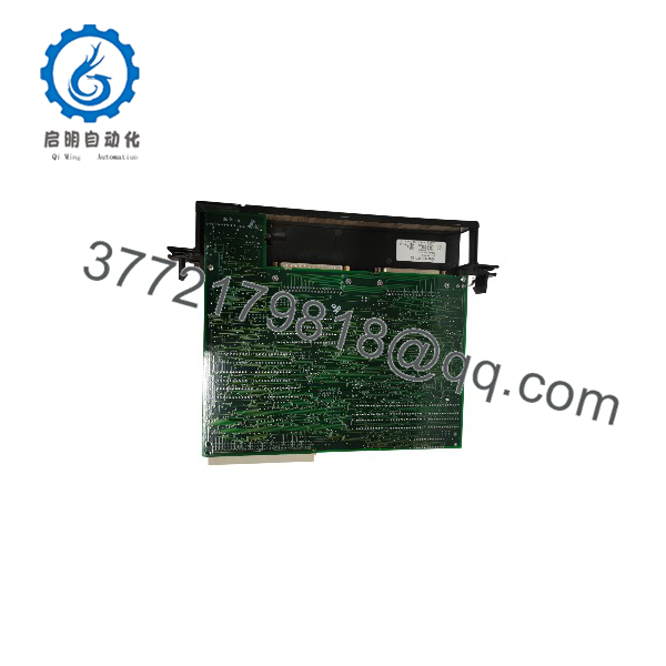
IC697RCM711
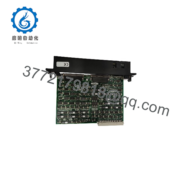
IC697RCM711
Installation & Configuration Guide
Stage 1 — Pre-Installation Preparation
- Confirm the exact part number: Verify the replacement is IC697RCM711, not another Series 90-70 communications module.
- Confirm that both redundant PLC systems use compatible redundancy CPUs.
- Review the existing redundancy configuration and record the current rack/slot arrangement.
- Back up the PLC application and configuration before removing hardware.
- Inspect the redundancy cable, connectors, and associated BTM/BRM hardware.
- Verify the interconnecting cable remains within the documented 25 ft (7.5 m) total limit.
⚠️ Estimated time: 15–30 minutes, depending on system documentation and access.
Stage 2 — Removing the Existing Module
- Place the redundant system in the appropriate maintenance state according to the site procedure.
- Do not remove the module while energized unless the installed system documentation specifically permits it.
- Record the existing LED status and cable routing.
- Disconnect the redundancy interface cable from the RCM.
- Release the module retaining hardware and remove the RCM from the rack.
- Inspect the backplane connector for contamination or mechanical damage.
⚠️ Removing an RCM from a live redundant system can affect CPU redundancy and system availability. Follow the plant’s approved maintenance procedure.
Stage 3 — Installing the IC697RCM711
- Verify the replacement module’s catalog number and hardware revision.
- Insert the RCM into the specified rack position.
- Ensure the module is fully seated in the backplane connector.
- Reconnect the upper interface to the appropriate BTM/BRM or redundancy communication path.
- Leave the lower connector unused as specified by the OEM documentation.
- Check cable routing and connector retention before restoring operation.
⚠️ Estimated time: 10–20 minutes.
Stage 4 — Power-On & Testing
- Restore power according to the approved startup sequence.
- Check the BOARD OK indication.
- Verify LOCAL READY and REMOTE READY conditions.
- Confirm the active/standby relationship using the LOCAL ACTIVE and REMOTE ACTIVE indicators.
- Verify that the redundant CPUs synchronize correctly.
- Confirm shared I/O data is available to both systems.
- If required by the maintenance procedure, perform a controlled redundancy transfer and confirm the standby CPU assumes control correctly.
- Record the final LED state and system diagnostics.
⚠️ The manual transfer pushbutton should only be used when the backup CPU is confirmed ready. OEM documentation also specifies a minimum interval between switch requests.
FAQ
What does the IC697RCM711 do?
It provides the communication path between the primary and secondary CPUs in a Series 90-70 redundant PLC system. Its functions include CPU synchronization and transfer of shared I/O data.
Which CPUs are supported?
The documented Hot Standby configurations support IC697CPU780, IC697CGR772, and IC697CGR935 CPUs. Compatibility should be checked against the specific redundancy architecture and software revision.
Where is the RCM711 installed?
The RCM is installed in rack 0. The module datasheet specifies slots 2 through 9 for the RCM, while the redundancy user guide also requires the RCM to be positioned without an empty slot between it and the CPU. Follow the applicable system manual for the exact rack configuration.
What is the maximum cable distance?
The OEM datasheet specifies up to 25 ft (7.5 m) total interconnecting cable between the redundancy systems.
Is still a current GE Fanuc product?
No. It is a legacy Series 90-70 component, and distributor documentation identifies it as discontinued. Replacement inventory therefore commonly comes from surplus, used, or refurbished channels.
Does replacing the RCM711 require reprogramming the PLC?
The RCM is a hardware redundancy communications module rather than the CPU containing the application program. However, the replacement should be checked against the existing redundancy configuration and software revision before installation. Do not assume that replacing the hardware alone resolves a redundancy fault.
What should I verify before purchasing a replacement?
Verify the full catalog number, hardware revision, physical condition, connector condition, and tested redundancy status. For a legacy system, also confirm compatibility with the installed CPU models and redundancy software before substituting a different revision.



