
 WhatsApp: +86 16626708626
 Email:
  Phone: +86 16626708626
Description
3. Key Technical Specifications
| Parameter | Value |
| Nominal Input Voltage | 120/240 VAC or 125/250 VDC |
| Input Voltage Range | 85 to 264 VAC (47 to 63 Hz) / 100 to 300 VDC |
| Total Maximum Output Power | 350 Watts |
| +5 VDC Output capacity | 60 Amps maximum |
| +12 VDC Output Capacity | 3.5 Amps maximum |
| −12 VDC Output Capacity | 1.0 Amp maximum |
| +3.3 VDC Output Capacity | 25 Amps maximum |
| Holdup Time (Power Ride-Through) | 20 milliseconds minimum at full load |
| Chassis Slot Width | Double-width slot form factor (Must occupy dedicated power slots) |
| Battery Connections | 3-pin front connector for lithium CMOS memory backup battery |
| Status Indicators | Front-panel LEDs: Power, Factory OK, Battery Low, Over-temperature |
| Protection Systems | Internal short-circuit, overvoltage, overcurrent, and thermal shutdown |
4. Product Introduction & Supply Chain Strategy
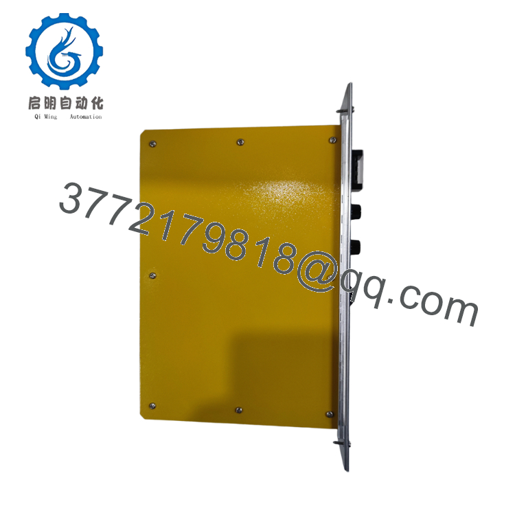
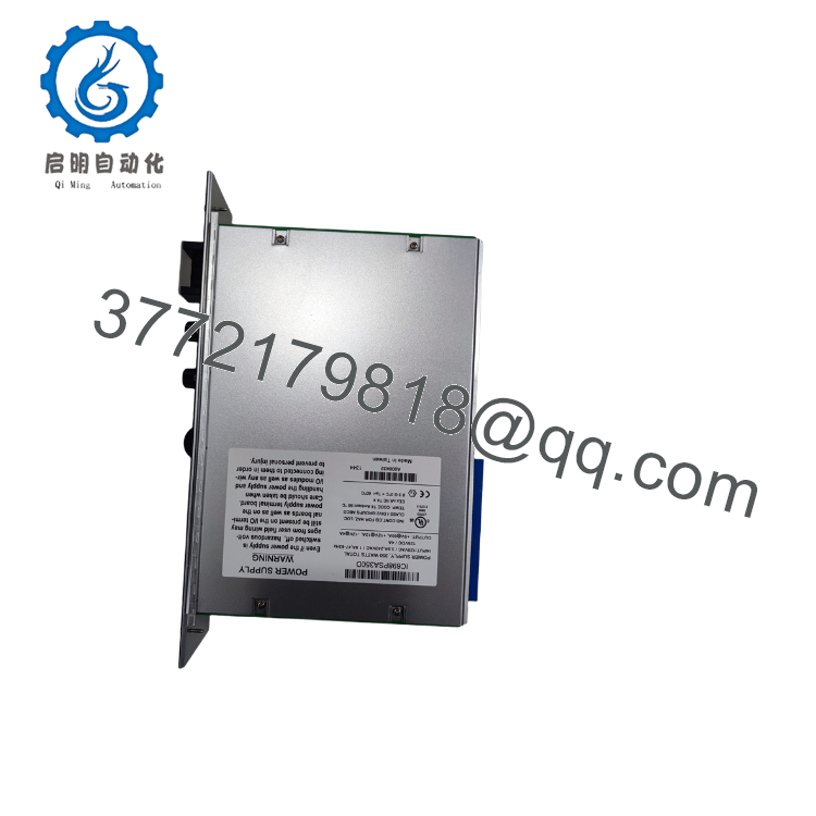
The GE Fanuc IC698PSA350 is a high-output 350 Watt power supply module engineered specifically to provide foundational power for the high-bandwidth PACSystems RX7i mainframe platform. Occupying a double-width slot configuration on the baseplate, this premium module accepts wide-range AC utility power or high-voltage DC battery links. It efficiently conditions input power into highly regulated +5 VDC, +3.3 VDC, +12 VDC, and −12 VDC voltage rails, satisfying the heavy current consumption demands of fast Celeron/Pentium processors, high-speed VME64 modules, and dense fiber communication cards.
From a Total Cost of Ownership (TCO) perspective, the IC698PSA350 is a classic Single Point of Failure (SPOF) component. Since the entire RX7i product family is obsolete, a primary power supply breakdown immediately forces a total rack blackout, dropping critical SCADA communication links and field bus networks. Sourcing this module as a certified New Surplus spare provides a superior risk mitigation strategy over third-party refurbished units, which often harbor dried-out filter capacitors and heat-stressed transformers. Keeping 1–2 zero-hour factory surplus supplies in buffer stock ensures immediate recovery and keeps production running while long-term migration paths are engineered.

- IC698PSA350
- IC698PSA350
5. Installation & Configuration Guide
Stage 1: Pre-Installation (Prep & Safety)
Enforce absolute lock-out/tag-out (LOTO) protocols on the primary plant feeder lines supplying the rack enclosure. Verify that all external incoming power lines are completely dead using a certified digital multimeter. Secure a grounded ESD wrist strap to your arm and clamp its lead to an unpainted metal surface on the control cabinet frame. Before handling the replacement supply, check that you have a fresh lithium battery pack on hand to preserve the CPU logic tables during the physical swap.
Stage 2: Removal
Loosen the upper and lower faceplate retaining screws securing the module to the rack frame. Unplug the terminal block connector strip from the front face of the card to leave the field wiring intact. Disconnect the internal CMOS memory backup battery lead from the 3-pin terminal on the front plate. Simultaneously pivot the top and bottom card ejector clips outward to disengage the backplane power pins, then slide the module horizontally out of the slot tracks.
Stage 3: Installation (Clone & Seat)
Verify that the replacement IC698PSA350 has clean, unscored backplane connector pins and that its input configuration switches match the incoming line setup (AC vs. DC). This module must always be inserted into the designated leftmost power slots of the RX7i rack chassis. Align the card with the upper and lower plastic slot guides, slide it inward, and lock the top and bottom ejector clips to seat the high-current backplane interface completely. Secure the faceplate retaining screws and plug in the fresh logic backup battery pack.
Stage 4: Power-On & Testing
Re-seat the main wired power terminal block assembly. Restore primary line power to the rack. Monitor the front panel indicator lights immediately: the “Power” LED must shine a solid green, indicating all internal DC outputs are operating within regulation parameters. The CPU module adjacent to it should successfully clear its boot cycle, and the “Battery Low” LED must remain completely unlit, confirming the memory backup loop is fully pressurized.
6. Firmware/Software Versions & Upgrade Notes
The IC698PSA350 operates as a purely analog and hardware-driven power conversion assembly, meaning it does not host a flash firmware operating system or microprocessor microcode.
⚠️ CRITICAL BACKPLANE LOADING BALANCE: While this power supply does not require software configuration, it requires rigid consideration of your backplane power budget. It delivers up to 60 Amps on the +5 VDC line and 25 Amps on the +3.3 VDC line. When compiling high-end RX7i redundancy racks featuring 700 MHz CPUs (such as the IC698CRE040-HN) along with multiple high-density network transceivers, add up the combined milliamp ratings specified for each card. Exceeding the 350 Watt overall thermal threshold or overcurrent boundaries will trip the module’s internal protection, leading to sudden shutdown cycles or spontaneous system drops.
7. Frequently Asked Questions (FAQ)
What is the purpose of the 3-pin battery connector on the front panel?
The 3-pin connector houses the plug for the external lithium battery pack. This battery loop travels across the backplane traces to maintain the volatile CMOS memory (holding your application logic and active register tables) inside the adjacent CPU module whenever primary power is disconnected. To prevent data loss, always change this battery while the main power supply is active and running.
Is this IC698PSA350 unit brand new, or is it a pulled/refurbished part?
This product is a Brand New Surplus unit. It is not used, not pulled from a decommissioned plant, and not refurbished. All modules undergo rigorous quality verification to ensure OEM-level reliability. Every power supply is stored within sealed anti-static protective packaging, showing pristine gold edge connectors, flawless internal component layouts, and zero track adjustments.
Can this power supply module be hot-swapped while the rack is active?
No. The legacy RX7i backplane architecture does not feature hot-swap capability for its primary power units. Attempting to pull or insert the IC698PSA350 while the main incoming power line is live will create massive electrical arcs across the high-current backplane pins. This can permanently burn out the backplane contacts, instantly destroy adjacent CPU/analog cards, and present a severe arc-flash safety hazard to the technician. Always isolate the incoming line power before swapping the hardware.
Does this module automatically adjust between AC and DC input types?
Yes, the IC698PSA350 features a universal wide-range front-end rectifier that accepts both 85–264 VAC and 100–300 VDC inputs natively. However, you must always double-check your external terminal block wiring configuration and ensure your grounding scheme matches the incoming supply line type according to standard industrial safety practices.
What warranty terms apply to this obsolete surplus power supply?
We back this New Surplus IC698PSA350 module with a comprehensive 1-year operational warranty from your date of purchase. If a component defect occurs during this window, we handle replacement or repair immediately, shielding your operating budget from the limited 30-day structural warranties typically packaged with refurbished alternative components.



