
 WhatsApp: +86 16626708626
 Email:
  Phone: +86 16626708626
Description
3. Key Technical Specifications
| Parameter | Value |
|---|---|
| Model Number | GF868-1-2 |
| Manufacturer | GE Panametrics (Baker Hughes) |
| Product Type | Ultrasonic Flare Gas Mass Flowmeter |
| Measurement Principle | Patented Correlation Transit-Time™ Ultrasonic |
| Measured Parameters | Mass flow, actual flow, standard flow, totalized flow, velocity |
| Typical Applications | Flare gas, vent gas, hydrocarbon gas, biogas |
| Pipe Size | 2 in to 120 in (50 mm to 3,000 mm) and larger |
| Velocity Range | ±0.3 to ±100 m/s (standard); optional up to 120 m/s |
| Accuracy | ±2% to ±5% (1-path); ±1.4% to ±3.5% (2-path), depending on installation |
| Repeatability | ±1% |
| Rangeability | Up to 3,940:1 |
| Enclosure | NEMA 4X / IP66 weatherproof; optional explosion-proof versions |
| Power Supply | 100–130 VAC, 200–265 VAC, or 12–28 VDC (configuration dependent) |
| Communications | RS-232, analog I/O, optional Modbus and additional I/O cards |
4. Product Introduction
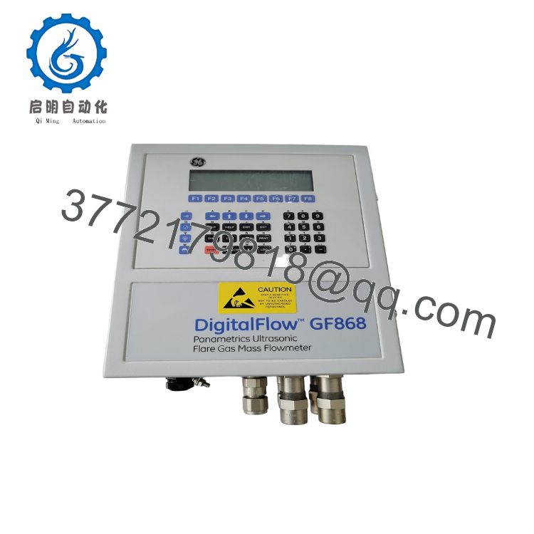
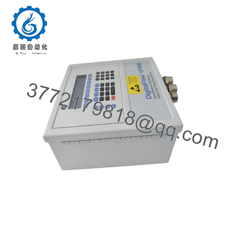
The GE Panametrics GF868-1-2 is an ultrasonic flare gas flowmeter developed for continuous measurement of flare and vent gas in refineries, petrochemical plants, LNG facilities, and power generation sites. Using the patented Correlation Transit-Time™ ultrasonic technology, it measures flow without introducing pressure loss or moving parts.
Unlike differential-pressure flowmeters, the GF868 maintains reliable measurement over an extremely wide flow range while requiring minimal routine maintenance. It supports mass flow, actual and standard volumetric flow, totalization, molecular weight estimation, and speed-of-sound calculations when pressure and temperature inputs are available.

- GF868-1-2
- GF868-1-2
5. Installation & Configuration Guide
Stage 1 – Pre-Installation Preparation (20–30 minutes)
⚠️ Safety First
- Notify plant operations before beginning work.
- Follow Lock-Out/Tag-Out (LOTO) procedures.
- Verify the flare header is in a safe operating condition.
- Confirm hazardous-area requirements before opening the enclosure.
- Wear appropriate PPE and use an ESD wrist strap when servicing electronics.
Tools Required
- ESD wrist strap
- Phillips screwdriver
- Digital multimeter
- Ultrasonic transducer alignment tools
- Laptop with GF868 programming software
- Smartphone for installation photos
Data Backup
- Export all flowmeter configuration files.
- Record communication parameters.
- Save calibration constants.
- Photograph terminal wiring.
- Record transducer mounting locations.
Stage 2 – Removing the Existing Unit (15–20 minutes)
- Disconnect auxiliary power.
- Label all field wiring.
- Disconnect communication cables.
- Remove transmitter enclosure connections.
- Remove transducer cables carefully.
- Inspect cable glands and connector seals.
⚠️ Do not remove or reposition ultrasonic transducers unless replacement or recalibration is required.
Stage 3 – Installing the New Unit (20–30 minutes)
- Verify the complete model number GF868-1-2.
- Install the transmitter enclosure securely.
- Reconnect ultrasonic transducer cables.
- Restore analog and digital communications.
- Reload the original configuration file.
- Verify pipe dimensions, gas composition, and transducer spacing.
Self-Checklist
- ✔ Model verified
- ✔ Power supply correct
- ✔ Transducers connected
- ✔ Communication restored
- ✔ Configuration loaded
Stage 4 – Power-On & Functional Testing (20 minutes)
Pre-Power Checks
- Verify input voltage.
- Confirm cable shielding is properly grounded.
- Inspect all enclosure seals.
Startup Procedure
- Apply power.
- Verify successful self-test.
- Confirm ultrasonic signal strength.
- Verify pressure and temperature inputs.
- Compare measured flow with plant reference values.
- Confirm SCADA communication.
- Verify alarm outputs and totalizers.
⚠️ Troubleshooting
- Weak ultrasonic signal: Check transducer spacing, alignment, and cable condition.
- Flow reading unstable: Verify straight pipe lengths and gas composition settings.
- No SCADA communication: Confirm RS-232 or Modbus configuration.
- Zero flow with active process: Inspect transducer orientation and configuration.
6. Frequently Asked Questions (FAQ)
Q1. Does the GF868 require pipe cutting?
No. The GF868 uses externally mounted ultrasonic transducers, allowing installation without cutting the pipe or interrupting process pressure. This significantly reduces installation time and eliminates pressure loss.
Q2. What gases can the GF868 measure?
It is designed for flare gas, vent gas, hydrocarbon gases, biogas, digester gas, and other industrial gases commonly found in refinery and petrochemical applications.
Q3. Is this suitable for custody transfer?
No. The GF868 is primarily intended for flare management, emissions monitoring, and process control. Custody transfer applications typically require flowmeters specifically certified for fiscal measurement.
Q4. Can one transmitter measure two flare lines?
Yes. Depending on the installed option package, the GF868 supports a dual-channel configuration that can monitor two separate pipes or provide dual-path averaging on a single line.
Q5. Why does flare gas measurement require ultrasonic technology?
Flare systems experience rapid flow changes, reverse flow, low pressure, and highly variable gas composition. Transit-time ultrasonic measurement offers a wide operating range, no moving parts, and negligible pressure loss, making it well suited to these conditions.
Q6. Why is my flow reading unstable after replacing the electronics?
In field commissioning, the electronics are rarely the root cause. Verify:
- Transducer spacing
- Pipe dimensions
- Gas composition
- Pressure and temperature inputs
- Communication parameters
A small configuration mismatch can produce large measurement errors, even when the transmitter passes its self-test.
Q7. What should be verified before returning the meter to service?
An experienced instrumentation engineer should confirm:
- Correct model and option code
- Proper transducer spacing and orientation
- Stable ultrasonic signal quality
- Accurate pipe and gas configuration
- Pressure and temperature input calibration
- SCADA communication
- Analog output scaling
- Alarm and totalizer operation
Completing these checks minimizes commissioning time and helps ensure reliable flare gas measurement throughout the operating life of the system.



