
 WhatsApp: +86 16626708626
 Email:
  Phone: +86 16626708626
Description
3. Key Technical Specifications
| Parameter | Specification |
| Manufacturer | General Electric (GE Energy / GE Vernova / Syprotec) |
| Part Number | H201CI-1 (Also styled as H201Ci-1) |
| Compatible Transmitters | 1x Hydran 201Ti Intelligent Gas Transmitter |
| Integrated Display | Digital Light-Emitting Diode (LED), 0–1999 ppm scale range |
| Primary Analog Output | Configurable via jumpers: 4–20 mA, 0–1 mA, 0–1 V, or 0–10 V |
| Secondary Analog Output | Optional isolated loop, 1500 V RMS isolation baseline |
| Dry Contact Relays | Gas Hi, Gas Hi-Hi, System Fail (Form C, SPDT, 125 VA @ 250 Vac, 60 W @ 220 Vdc) |
| Supervisory Link Interface | 3000 V opto-isolated link port; max loop length 1,300 m (4,000 ft) via twisted triad |
| Network Interfaces | 1x RS-485 port (daisy-chain up to 32 units) | 1x Local DB-9 RS-232 serial port |
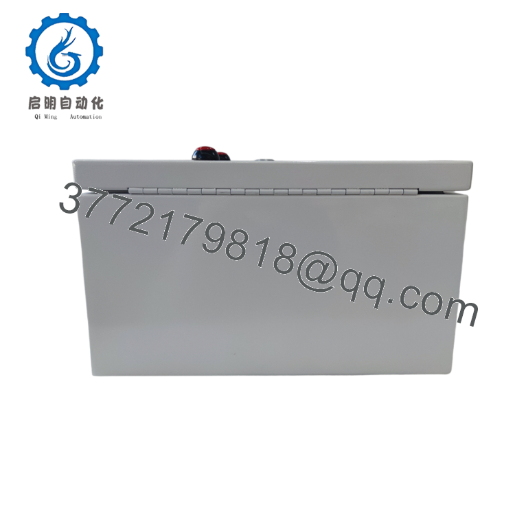
| Enclosure Protection | NEMA 4X (IP66) certified steel casing with textured baked-enamel white finish |
| Climate Regulation | Integrated internal thermostat-controlled space heater assembly |
| Operating Temperature | −50 to +55°C (−58 to +131°F) environmental tolerance |
| Power Requirements | Switchable input: 100 / 115 / 200 / 230 Vac, ±10%, 50/60 Hz, 120 VA max |
4. Product Introduction & Supply Chain Strategy
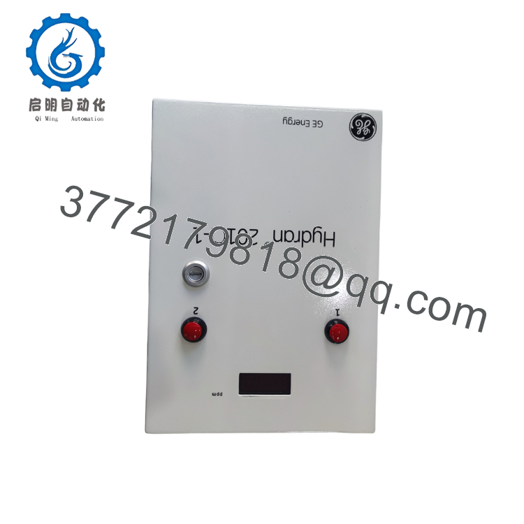
The GE Hydran H201CI-1 is a dedicated, single-channel remote electronic controller designed to pair directly with a Hydran 201Ti intelligent transmitter. Installed externally on a transformer tank’s oil valve, this NEMA 4X-rated controller acts as an accessible human-machine interface (HMI) and communication node for tracking key Dissolved Gas Analysis (DGA) signatures—primarily hydrogen and fault-gas composites. It handles real-time loop scaling, displays current ppm counts, and triggers physical Form C dry-contact alarms when sudden hourly or daily gas generation trends indicate arcing or thermal decomposition inside the transformer oil insulation system.
From a reliability and procurement perspective, the H201CI-1 is a critical asset defense unit. Because this series has transitioned to legacy status, sourcing factory-sealed New Surplus inventory is the safest approach to maintain grid monitoring uptime. Used or refurbished controllers pose a significant Total Cost of Ownership (TCO) risk; their internal enclosure space heaters and opto-isolation circuits frequently experience thermal wear from years of outdoor exposure. A failure in a used isolation barrier can send transient high-voltage surges downstream into control-room SCADA boards. Investing in a New Surplus H201CI-1 ensures clean, factory-certified circuit insulation and prevents unmonitored transformer operating windows.

- H201CI-1
- H201CI-1
5. Installation & Configuration Guide
Stage 1: Pre-Installation (Prep & Safety)
- Power Isolation: Open the upstream AC supply breaker feeding the controller panel enclosure. Verify that all incoming line terminals measure 0 Vac using an insulated digital multimeter.
- Conduit Audit: Confirm that all interconnecting supervisory lines, alarm wiring, and power feeds are enclosed within rigid, grounded steel conduits to optimize mechanical and EMI protection.
- ESD Prevention: Affix a grounded ESD wrist strap prior to interacting with the internal circuit boards or setting jumper configurations.
Stage 2: Removal
- Disconnect Wiring: Unclamp all incoming terminal wires, including the 3-wire supervisory link cable from the 201Ti transmitter, the 4–20 mA analog loops, and the alarm contact arrays.
- Chassis Unmounting: Unscrew the enclosure from its outdoor support frame or anti-vibration isolation mounts.
- Safe Extraction: Carefully remove the housing assembly, keeping it upright to protect the door-mounted LED display components.
Stage 3: Installation (Clone & Seat)
- Mechanical Mounting: Bolt the new New Surplus H201CI-1 enclosure onto the anti-vibration mount framework. Ensure all weatherproofing door gaskets seat smoothly without crimping.
- Voltage Selection Verification: Check the internal transformer tapping configuration to ensure the internal power assembly matches your site’s local utility supply voltage (e.g., 115 Vac vs. 230 Vac) prior to energizing.
- Jumper Configuration: Mirror the precise analog output jumper settings from the old board onto the new module’s mother board to maintain consistent 4–20 mA or 0–10 V loop telemetry.
- Termination: Reconnect all cables to the designated internal terminal strips, ensuring the shield drains for the supervisory link are properly terminated to the chassis ground ground rail.
Stage 4: Power-On & Testing
- Initial Energization: Apply AC control power to the enclosure loop.
- Visual Boot Audit: Confirm the digital LED display initializes and illuminates clearly. If a system failure state is active, the display will blank out automatically.
- Loop Loopback Validation: Test the Gas Hi and Gas Hi-Hi pushbuttons located on the enclosure door. Verify they correctly lock closed when pressed, engage their respective remote alarm contacts, and clear cleanly when pressed a second time.
6. Firmware/Software Versions & Upgrade Notes
The H201CI-1 utilizes hardware-based logic mapping combined with fixed microcontroller firmware on its internal digital board assembly. Real-time telemetry is typically pushed out using either standard Modbus RTU or native Hydran protocol layers over the isolated RS-485 link interface.
When integrating a New Surplus unit into a larger, multi-node daisy-chain network (up to 32 controllers over a single 1,300-meter line segment), verify that the network baud rates and device node addresses are configured identically within your master monitoring package, such as GE’s Perception software. If the new controller uses a newer internal revision than the existing network nodes, verify that your computer’s local RS-232 interface setup supports standard 9-pin DB-9 serial handshakes without requiring old driver legacy workarounds.
7. Frequently Asked Questions (FAQ)
- Why should I source a New Surplus H201CI-1 instead of a cheaper, repaired or refurbished unit? A refurbished unit has often spent years mounted outdoors beside heavy power transformers, leaving it exposed to extreme seasonal temperatures and high vibrational stress. These conditions degrade the internal power-supply capacitors and compromise the door-mounted alarm button seals. Buying a New Surplus controller ensures you receive zero-hour components, a pristine NEMA 4X steel enclosure, and factory-certified insulation barriers.
- What exactly happens to the controller outputs if the system detects an internal failure? If the controller detects a critical fault—such as a loss of communication with the 201Ti sensor, a power failure, or a compromised gas cell—the H201CI-1 automatically forces its analog output loop down to 0 mA. Concurrently, it activates the Form C “Fail” relay and blanks out the front LED display. This clear distinction prevents control rooms from misinterpreting a system fault as a safe, zero-ppm gas reading.
- Can the H201CI-1 controller be mounted directly on the transformer tank along with the transmitter? No. While the 201Ti transmitter mounts directly to the transformer’s oil sampling valve, the H201CI-1 controller enclosure must be mounted separately on a nearby, vibration-free structure or dedicated pedestal. High transformer casing vibration can damage the internal digital boards and cause false relay trips if not isolated by anti-vibration mounts.
- Does this unit contain its own internal climate control system for cold-weather operation? Yes. Every standard H201CI-1 includes an internal, thermostat-controlled space heater assembly. This integrated heating network allows the internal electronics, LED displays, and terminal blocks to operate efficiently in ambient outdoor conditions down to −50°C (−58°F).
- How many gas transmitters can a single H201CI-1 controller manage simultaneously? The H201CI-1 is designed as a single-channel remote interface, meaning it supports only one Hydran 201Ti intelligent transmitter. If your facility requires centralized monitoring for multiple adjacent transformer phases or separate tanks on a single panel, you will need to utilize the multi-channel variant, known as the H201Ci-C.



