
 WhatsApp: +86 16626708626
 Email:
  Phone: +86 16626708626
Description
3. Key Technical Specifications
| Parameter | Value |
|---|---|
| Model Number | HE693RTM705 |
| Manufacturer | Horner APG for GE Fanuc |
| Product Type | RTU Master Communication Module |
| PLC Family | GE Fanuc Series 90-30 |
| Communication Protocol | Modbus RTU Master |
| Communication Channels | 2 Independent Master Channels |
| Port Configuration | RS-232, RS-422, RS-485 (configuration dependent) |
| Supported Connections | Direct, Multi-drop, Radio Modem, Dial-in, Dial-out |
| Maximum Modbus Transfer | Up to 250 bytes per command |
| PLC Compatibility | Series 90-30 CPU331 or higher |
| Installation | Local rack slot only (not expansion rack) |
| Backplane Power Consumption | 425 mA @ 5 VDC |
| Application | PLC-to-RTU communications, SCADA integration, remote I/O networks |
4. Product Introduction
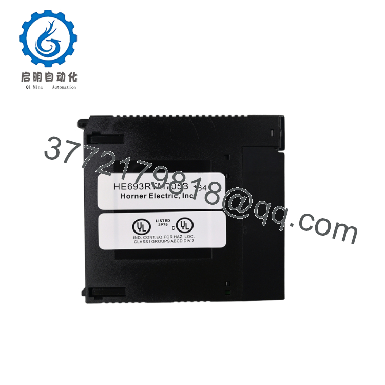
The GE HE693RTM705 is a dedicated RTU Master Communication Module developed by Horner APG for the GE Fanuc Series 90-30 PLC platform. It enables a PLC to function as a Modbus RTU master, allowing communication with multiple remote RTUs, PLCs, intelligent instruments, and field devices over serial communication networks.
The module provides two independent communication channels that can operate simultaneously using RS-232, RS-422, or RS-485 interfaces. Each channel supports direct serial links, multidrop networks, radio modems, and dial-up applications, making it suitable for water treatment, power distribution, oil and gas facilities, and industrial SCADA systems. It does not support Modbus Plus.

- HE693RTM705
5. Installation & Configuration Guide
Stage 1 – Pre-Installation Preparation (10 minutes)
⚠️ Safety First
- Notify operations before stopping the PLC.
- Apply Lock-Out/Tag-Out (LOTO) procedures.
- Remove power from the Series 90-30 rack.
- Wait at least 5 minutes before servicing.
- Wear an ESD wrist strap throughout the installation.
Tools Required
- ESD wrist strap
- Phillips screwdriver
- Digital multimeter (Fluke 115 or equivalent)
- RS-232/RS-485 communication tester (optional)
- Laptop with Logicmaster 90 or compatible programming software
- Smartphone for wiring documentation
Data Backup
- Upload the PLC project.
- Save communication configuration tables.
- Record baud rate, parity, slave addresses, and timeout settings.
- Photograph every serial connector before removal.
Stage 2 – Removing the Existing Module (5–10 minutes)
- Turn off rack power.
- Label every communication cable.
- Disconnect both serial ports.
- Release the module retaining clip.
- Remove the module straight out from the rack.
- Inspect the backplane connector for bent pins or contamination.
⚠️ Keep the original module until all communication tests have passed.
Stage 3 – Installing the New Module (10 minutes)
- Verify the complete part number HE693RTM705.
- Confirm the PLC uses CPU331 or a higher-performance CPU, as lower-end embedded CPUs are not supported.
- Install the module into a local rack slot.
- Secure the retaining clip.
- Reconnect serial communication cables.
- Download the communication configuration if required.
Self-Checklist
- ✔ Correct model installed
- ✔ Local rack slot used
- ✔ CPU compatibility confirmed
- ✔ Serial wiring verified
- ✔ Communication parameters restored
Stage 4 – Power-On & Functional Testing (15–20 minutes)
Pre-Power Checks
- Verify 5 VDC rack power.
- Check RS-232/RS-485 wiring polarity.
- Confirm communication termination resistors where required.
Startup Procedure
- Power the PLC rack.
- Verify the module initializes successfully.
- Confirm ladder logic initializes the RTM module.
- Monitor communication status registers.
- Read several Modbus slave registers.
- Verify write commands execute correctly.
- Confirm stable communications with all remote RTUs.
⚠️ Troubleshooting
- No communication: Verify baud rate, parity, and slave address.
- CRC errors: Check RS-485 wiring polarity and cable shielding.
- Module not recognized: Verify installation in a local rack and compatibility with CPU331 or higher.
- Intermittent polling failures: Inspect termination resistors and network length.
6. Frequently Asked Questions (FAQ)
Q1. What is the primary function of the HE693RTM705?
The module allows a Series 90-30 PLC to operate as a Modbus RTU master, communicating with multiple remote slave devices including PLCs, RTUs, power meters, and intelligent field instruments.
Q2. How many communication ports does the module provide?
The HE693RTM705 provides two independent Modbus RTU master channels. Each channel can be configured separately for RS-232, RS-422, RS-485, radio modem, multidrop, dial-in, or dial-out applications.
Q3. Is the HE693RTM705 compatible with every Series 90-30 CPU?
No. The module requires a CPU331 or higher. It is not compatible with the smaller embedded CPUs such as the CPU311, CPU313, or CPU323, and it must be installed in a local rack, not an expansion rack.
Q4. Does this module support Modbus Plus?
No. The HE693RTM705 supports Modbus RTU Master communications only. It does not support Modbus Plus (MB+).
Q5. Can I hot-swap the communication module?
No. The Series 90-30 platform was not designed for hot replacement of communication modules. Power down the rack before removing or installing the module to avoid communication faults or hardware damage.
Q6. Why should I document the serial communication settings before replacement?
This is one of the most common field mistakes. If baud rate, parity, timeout, or slave addressing is restored incorrectly, the PLC may appear healthy while all remote communications fail. Taking photographs and exporting configuration data before replacement can save hours of troubleshooting.
Q7. What should be verified before returning the PLC system to service?
A commissioning engineer should confirm:
- Correct module model and revision
- CPU331 (or higher) compatibility
- Installation in a local rack slot
- RS-232/RS-422/RS-485 wiring integrity
- Correct Modbus communication parameters
- Successful polling of all slave devices
- Stable communication status with no CRC or timeout errors
- Proper ladder logic initialization of the RTU Master module
Completing these verification steps minimizes commissioning time and helps ensure reliable Modbus RTU communications throughout the automation system.



