
 WhatsApp: +86 16626708626
 Email:
  Phone: +86 16626708626
Description
3. Key Technical Specifications
| Parameter | Value |
|---|---|
| Model Number | IC200ALG264H |
| Manufacturer | GE Fanuc (Emerson) |
| Product Type | Analog Current Input Module |
| Series | VersaMax I/O |
| Number of Channels | 15 single-ended current inputs |
| Input Ranges | 4–20 mA or 0–20 mA (jumper selectable) |
| A/D Resolution | 15-bit |
| Update Rate | 7.5 ms |
| Accuracy | ±0.3% typical, ±0.5% maximum of full scale (25 °C) |
| Input Filter | 24 Hz ±20% |
| Backplane Power Consumption | 100 mA @ +5 VDC |
| External Module Power | Not required (field transmitters require external supply) |
| LED Indicators | OK LED, Internal Power LED |
| Typical Applications | Process control, pressure, temperature, flow, and level signal acquisition |
4. Product Introduction
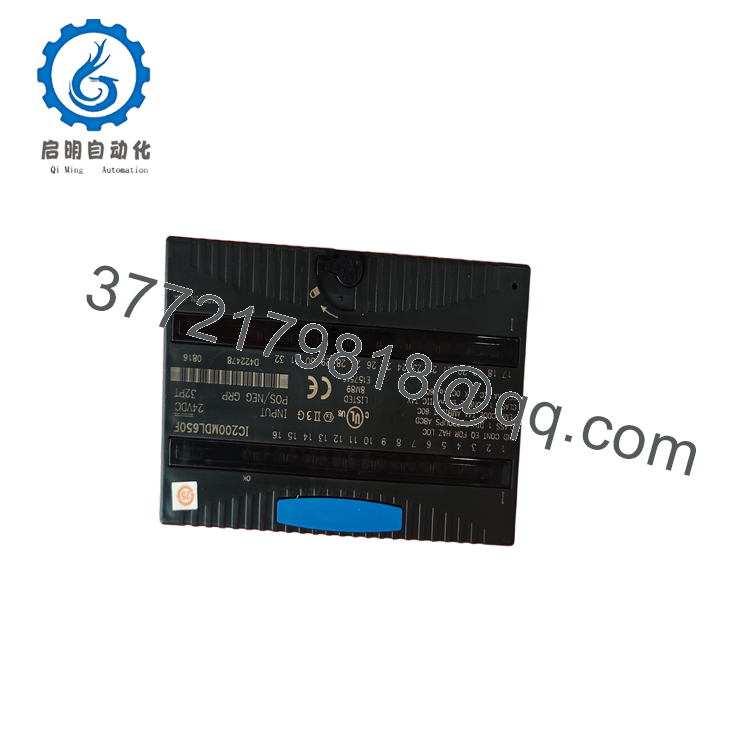
The GE IC200ALG264H is a VersaMax 15-channel analog current input module designed to interface industrial transmitters with GE VersaMax PLC systems. It accepts either 4–20 mA or 0–20 mA input signals and converts them into high-resolution digital values for process monitoring and control.
The module receives operating power directly from the VersaMax backplane and supports software diagnostics, including open-wire detection when operating in 4–20 mA mode. Revision H introduced labeling updates only, with no changes to compatibility, functionality, or electrical performance compared to previous revisions.
5. Installation & Configuration Guide
Stage 1 – Pre-Installation Preparation (10 minutes)
⚠️ Safety First
- Notify operations before shutting down the PLC.
- Apply Lock-Out/Tag-Out (LOTO).
- Remove power from the VersaMax I/O station.
- Wait at least 5 minutes before removing the module.
- Wear a grounded ESD wrist strap.
Tools Required
- ESD wrist strap
- Phillips screwdriver
- Digital multimeter (Fluke 115 or equivalent)
- Wire labels
- Smartphone for wiring documentation
Data Backup
- Save the PLC hardware configuration.
- Record channel scaling parameters.
- Photograph terminal wiring.
- Record jumper position (4–20 mA or 0–20 mA).
Stage 2 – Removing the Existing Module (5–10 minutes)
- Remove system power.
- Label every field wire.
- Disconnect the terminal block.
- Release the retaining latch.
- Pull the module straight from the carrier.
- Inspect carrier contacts for contamination or bent pins.
⚠️ Keep the existing module until commissioning has been completed successfully.
Stage 3 – Installing the New Module (10 minutes)
- Verify the model number IC200ALG264H.
- Confirm the input range jumper matches the application.
- Install the module firmly onto the VersaMax carrier.
- Reconnect the field wiring.
- Restore the PLC hardware configuration if necessary.
- Verify the analog channel mapping.
Self-Checklist
- ✔ Correct module installed
- ✔ Jumper configuration verified
- ✔ Terminal block secured
- ✔ Field wiring checked
- ✔ Carrier fully engaged
Stage 4 – Power-On & Functional Testing (15 minutes)
Pre-Power Checks
- Verify +5 VDC backplane power.
- Check transmitter loop wiring.
- Confirm no wiring shorts.
Startup Procedure
- Apply power to the PLC.
- Verify the OK and INT PWR LEDs illuminate normally.
- Confirm the CPU recognizes the module.
- Measure several 4–20 mA loops.
- Verify engineering-unit scaling in the PLC.
- Compare displayed values with calibrated field instruments.
⚠️ Troubleshooting
- Open-wire alarm: Inspect loop continuity and transmitter wiring (available only in 4–20 mA mode).
- Incorrect analog values: Verify jumper selection and PLC scaling.
- No module recognition: Inspect carrier installation and backplane connection.
- Noisy measurements: Use shielded twisted-pair cable and ground the shield at one end only.

- IC200ALG264H
- IC200ALG264H
6. Frequently Asked Questions (FAQ)
Q1. What signals does the IC200ALG264H accept?
The module accepts 15 single-ended analog current inputs, configurable as 0–20 mA or 4–20 mA through a hardware jumper.
Q2. Does this module require an external power supply?
The module itself is powered by the VersaMax backplane. However, connected field transmitters require their own external loop power supply.
Q3. What changed in Revision H?
Revision H introduced labeling updates only. GE documentation states there were no changes to compatibility, functionality, or performance, making it suitable as a replacement for earlier compatible revisions.
Q4. Can this module detect an open transmitter loop?
Yes. When configured for 4–20 mA operation, the IC200ALG264H can report an open-wire fault for each input channel, simplifying field troubleshooting.
Q5. Can I hot-swap the IC200ALG264H?
Although some VersaMax systems support hot-swappable I/O under specific hardware configurations, replacement should be performed only if the installed carrier and controller explicitly support hot insertion. For most maintenance situations, powering down the I/O station before replacement remains the safest practice.
Q6. Why should I verify the jumper setting before startup?
A mismatch between the jumper configuration and the transmitter signal range is one of the most common commissioning errors. If the module is configured for 0–20 mA while the process uses 4–20 mA, measurements and fault diagnostics may be incorrect.
Q7. What should be verified before returning the system to service?
An experienced commissioning engineer should confirm:
- Correct module revision (IC200ALG264H)
- Proper 4–20 mA or 0–20 mA jumper configuration
- Stable +5 VDC backplane power
- Correct PLC hardware configuration
- Accurate analog scaling
- Open-wire diagnostics (if applicable)
- Shield grounding
- Stable readings from all 15 analog input channels
Completing these checks minimizes startup issues and ensures reliable analog signal acquisition throughout the VersaMax control system.



