
 WhatsApp: +86 16626708626
 Email:
  Phone: +86 16626708626
Description
3. Key Technical Specifications
| Parameter | Value |
|---|---|
| Model Number | IC200PWR102 |
| Manufacturer | GE Fanuc (Emerson) |
| Product Type | VersaMax AC Power Supply |
| Series | VersaMax I/O |
| Input Voltage | 85–132 VAC (120 VAC with jumper installed); 176–264 VAC (240 VAC without jumper) |
| Input Frequency | 47–63 Hz |
| Input Power | 27 VA |
| Output Voltages | 5 VDC and 3.3 VDC |
| Maximum Total Output Current | 1.5 A |
| Maximum 3.3 V Output | 1.0 A |
| 5 V Output | Up to 1.5 A minus the 3.3 V load |
| Protection | Short-circuit and overload protection |
| Hold-Up Time | 20 ms |
| Typical Installation | Mounted on CPU/NIU as the main station power supply or on a Power Supply Booster Carrier as supplemental power |
| Typical Applications | VersaMax PLC systems, distributed I/O stations, industrial automation |
4. Product Introduction
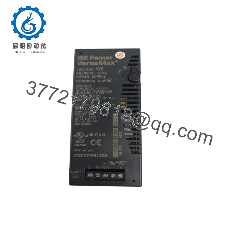
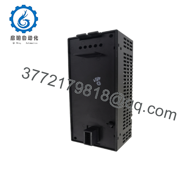
The GE IC200PWR102 is a 120/240 VAC VersaMax power supply module designed to provide regulated 5 VDC and expanded 3.3 VDC backplane power for VersaMax CPUs, Network Interface Units (NIUs), and I/O modules. It can serve either as the primary station power supply or as a supplemental power source when installed on a VersaMax Power Supply Booster Carrier.
The expanded 3.3 VDC capacity makes the IC200PWR102 suitable for systems containing newer VersaMax CPUs and communication modules with higher 3.3 V current requirements. Integrated overload and short-circuit protection help improve system reliability in demanding industrial environments.

- IC200PWR102
- IC200PWR102
5. Installation & Configuration Guide
Stage 1 – Pre-Installation Preparation (10 Minutes)
⚠️ Safety First
- Notify plant personnel before shutting down the PLC.
- Apply Lock-Out/Tag-Out (LOTO) procedures.
- Disconnect AC input power.
- Verify all stored energy has dissipated.
- Wear an ESD wrist strap during installation.
Required Tools
- Phillips screwdriver
- Digital multimeter
- ESD wrist strap
- Insulated screwdriver
- Wiring diagram
Backup Tasks
- Save the PLC hardware configuration.
- Record the installed power supply location.
- Photograph all wiring connections.
- Calculate total backplane current requirements.
Stage 2 – Removing the Existing Power Supply
- Turn OFF AC input power.
- Label the input wiring.
- Disconnect the AC power terminals.
- Release the retaining latch.
- Remove the power supply from the carrier.
- Inspect connectors and carrier contacts.
⚠️ Never replace the module while energized.
Stage 3 – Installing the Replacement Module
- Verify the model number IC200PWR102.
- Install the 120 VAC jumper only when operating from a 120 VAC source.
- Do NOT install the jumper when using 240 VAC input, as this can permanently damage the module.
- Mount the module securely.
- Connect AC input wiring.
- Verify total backplane current does not exceed the module rating.
Installation Checklist
- ✔ Correct model installed
- ✔ Input voltage verified
- ✔ Jumper correctly configured
- ✔ Wiring secure
- ✔ Current capacity confirmed
Stage 4 – Startup & Functional Test
Before Applying Power
- Verify AC input voltage.
- Confirm jumper position.
- Check protective earth connection.
Startup Procedure
- Apply AC power.
- Verify the power supply starts normally.
- Confirm CPU initialization.
- Verify all I/O modules power correctly.
- Check PLC diagnostics.
- Monitor system operation for several minutes.
⚠️ Troubleshooting
- No power: Verify AC input voltage and wiring.
- CPU fails to start: Check total backplane current and module seating.
- Power supply shuts down: Inspect for overloaded backplane or short circuit.
- Module damaged after startup: Verify the 120/240 VAC jumper was configured correctly.
6. Frequently Asked Questions (FAQ)
Q1. What is the primary function of the IC200PWR102?
The IC200PWR102 supplies regulated 5 VDC and expanded 3.3 VDC power to VersaMax CPUs, NIUs, and I/O modules through the PLC backplane. It may be used as either the main station power supply or a supplemental supply.
Q2. What input voltage does the IC200PWR102 accept?
The module operates from 120 VAC or 240 VAC. A jumper must be installed for 120 VAC operation and removed for 240 VAC operation. Using the jumper with 240 VAC input can damage the power supply.
Q3. How much output current is available?
The module provides a maximum combined output current of 1.5 A, with up to 1.0 A available on the 3.3 V output. The remaining capacity is available on the 5 V output.
Q4. Can the IC200PWR102 be used as a supplemental power supply?
Yes. In addition to serving as the primary power supply when mounted on a CPU or NIU, it can also be installed on a Power Supply Booster Carrier to provide supplemental backplane power for larger VersaMax I/O systems.
Q5. Is the IC200PWR102 still available?
Although it is a legacy VersaMax component, the IC200PWR102 remains available through industrial spare parts suppliers as New Surplus and professionally refurbished units, supporting long-term maintenance of existing PLC installations.
Q6. What is the most common installation mistake?
The most frequent error is incorrect jumper configuration. Installing the 120 VAC jumper while operating from a 240 VAC source can permanently damage the module, whereas omitting the jumper during 120 VAC operation prevents the specified hold-up performance.
Q7. What should be verified before returning the PLC system to service?
A commissioning engineer should confirm:
- Correct module (IC200PWR102)
- Proper 120/240 VAC jumper selection
- Stable AC input voltage
- Backplane current within the 1.5 A limit
- Normal CPU startup
- All I/O modules powered correctly
- No overload or fault diagnostics
- Stable PLC operation after commissioning
Completing these checks helps ensure reliable power distribution throughout the VersaMax PLC system and minimizes unexpected downtime.



