
 WhatsApp: +86 16626708626
 Email:
  Phone: +86 16626708626
Description
Key Technical Specifications
- Model: IC3645LXCD1
- Manufacturer: GE Industrial Systems / GE Fanuc
- Control Platform: EV100LX
- Assembly Type: EV100LX control cardbox assembly
- Typical Application: Electric forklift traction or pump control
- Logic Options: TX traction without BDI, TT traction with BDI, MX dual-motor traction without BDI, MT dual-motor traction with BDI, and PX pump control
- Nominal Vehicle Voltage: Application-specific; verify the vehicle nameplate and original control-card configuration
- Control Architecture: Solid-state motor-control assembly
- Feedback: Armature-current feedback through a series current sensor
- Adjustments: Current limit and control functions configured through the applicable EV100LX service handset
- System Protection: Current limiting and control override functions are application-dependent
- Physical Interface: Vehicle-specific power-base, motor, sensor, and control wiring
- Direct Replacement Status: Not confirmed from the base number alone; verify the complete suffix and board configuration
- Documentation Reference: EV100LX and EV200LX service documentation
- Operating Environment: Forklift enclosure environment; confirm temperature, vibration, and moisture limits from the vehicle manual
- Firmware: No separately documented PLC-style firmware version identified for the base cardbox number
- Protocol: No standard Ethernet, Modbus, Profibus, or EtherNet/IP interface should be assumed
- Compatibility Warning: Confirm vehicle model, battery voltage, traction/pump function, BDI option, and logic-card suffix before ordering
Product Introduction
The GE IC3645LXCD1 is an EV100LX solid-state control cardbox assembly used in GE-controlled electric forklift and industrial vehicle systems. It interfaces with the vehicle power base, motor circuitry, current-feedback sensor, control inputs, and application-specific logic card.
This base number is not sufficient to confirm a drop-in replacement. EV100LX configurations use suffixes such as TX, TT, MX, MT, and PX for traction, dual-motor, battery-discharge-indicator, and pump applications. Match the complete part number, vehicle model, battery voltage, and original card configuration before installation.
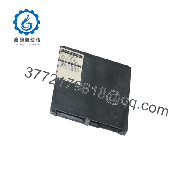
IC3645LXCD1
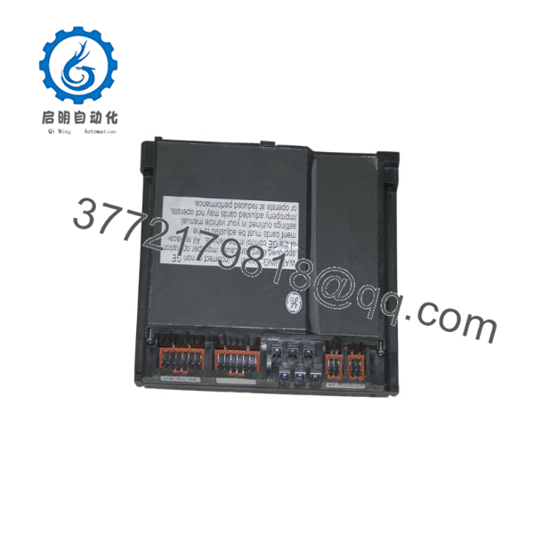
IC3645LXCD1
Installation & Configuration Guide
Stage 1: Pre-Installation Preparation — 10 to 15 Minutes
⚠️ Safety First: Remove the forklift from service, lower the forks or attachment fully, apply the parking brake, block the wheels, and follow the manufacturer’s battery-isolation procedure. Disconnect the battery and wait at least 5 minutes for capacitors in the control circuit to discharge.
Tools Required:
- ESD wrist strap and grounded ESD mat
- PH1 screwdriver and suitable nut drivers
- DC-rated multimeter
- Wire labels and marker
- Smartphone or camera for photographs
- Manufacturer-approved service handset, if required
- Insulated tools suitable for the battery voltage
Data and Configuration Backup:
- Record the forklift manufacturer, model, serial number, and battery voltage.
- Photograph the complete control cardbox, wire harness plugs, power connections, current sensor wiring, and logic-card labels.
- Record the complete suffix after IC3645LXCD1, if present.
- Identify whether the unit is configured for traction, pump, dual-motor traction, or BDI-equipped traction.
- Record current-limit settings and other service-handset parameters before disconnecting the old assembly.
- Confirm that the replacement is not merely a similar card with a different application suffix.
Stage 2: Removing the Old Module — 5 to 10 Minutes
- Verify that the battery is disconnected and that no hazardous DC voltage remains at the controller terminals.
- Label every wire and connector before removal. Use the photographs as a second reference.
- Disconnect control plugs, current-sensor wiring, motor connections, contactor wiring, and auxiliary connections as applicable.
- Do not pull on individual conductors or bridge terminals with a screwdriver.
- Remove the cardbox retaining hardware and withdraw the assembly straight from its mounting location.
- Inspect the mounting surface, harness plugs, bus connections, contactor wiring, and current sensor for heat damage or corrosion.
- Keep the old assembly available until the replacement has passed static and operational tests.
Stage 3: Installing the New Module — 10 to 15 Minutes
- Put on the grounded ESD wrist strap and verify the full replacement part number.
- Confirm that the logic-card application matches the vehicle: TX, TT, MX, MT, or PX where applicable.
- Verify the vehicle voltage and power-base arrangement against the removed assembly.
- Transfer only approved plug-in cards or configuration components. Do not move boards between assemblies unless the OEM procedure allows it.
- Install the control cardbox in the original orientation and secure all retaining hardware.
- Reconnect the harnesses using the labels and photographs. Ensure current-sensor polarity and motor connections match the original arrangement.
- Inspect all high-current terminals for looseness, discoloration, damaged insulation, or contamination.
- Check that no wire is trapped under the cardbox or exposed to moving parts.
Self-Checklist:
- Complete part number and suffix verified
- [] Vehicle voltage confirmed
- [] Traction or pump application confirmed
- [] BDI and dual-motor options checked
- [] Current-sensor wiring polarity verified
- [] Motor and contactor wiring secured
- [] Retaining hardware tightened
- [] Battery remains disconnected until final checks
Stage 4: Power-On and Testing — 15 to 30 Minutes
- Check for shorts between the battery-positive and battery-negative connections before reconnecting the battery.
- Verify that the accelerator, direction switch, seat switch, emergency stop, brake switch, and contactor circuits are in their safe states.
- Reconnect the battery under the manufacturer’s approved procedure.
- Check for unexpected contactor engagement, motor movement, or control-card heating before enabling travel.
- Use the service handset, where required, to verify current-limit and application settings.
- Raise the drive wheels clear of the floor for the initial no-load test only when the vehicle service procedure permits it.
- Test forward and reverse commands at low speed with the drive area controlled and personnel clear.
- Check acceleration, deceleration, regenerative braking, current limiting, and fault response.
- For pump configurations, test lift and hydraulic functions with the load secured and within the vehicle’s service limits.
- Return the vehicle to operation only after all safety interlocks and functional checks pass.
⚠️ Troubleshooting Note: If the vehicle will not move, check the battery voltage, emergency-stop circuit, seat or operator-presence circuit, direction input, contactor sequence, current-sensor wiring, and application suffix. Do not increase the current-limit setting to overcome a wiring or motor fault.
Frequently Asked Questions (FAQ)
What exactly is the GE IC3645LXCD1?
The IC3645LXCD1 is associated with the GE solid-state vehicle-control platform and is listed as an control cardbox assembly. It is used in electric forklift and industrial vehicle applications rather than standard PLC or DCS installations.
Is IC3645LXCD1 a complete drop-in replacement?
Not necessarily. The base number may require an application suffix such as TX, TT, MX, MT, or PX. Those suffixes identify different traction, pump, dual-motor, and battery-discharge-indicator configurations, so ordering only by the base number can produce a nonmatching controller.
Which forklift models use this control card?
The part is associated with several GE vehicle applications, including certain E/J1.25–1.75XL, E2.00–3.00XL, E3.50–5.50XL, J25–35B, N40–45FR, and R30E-series vehicles. The vehicle list is not universal; verify the exact model, serial range, battery voltage, and control suffix before purchase.
Can I hot-swap this control assembly?
No. Disconnect the battery and follow the forklift manufacturer’s electrical isolation procedure before removing the cardbox. Battery-powered vehicle controllers can retain hazardous energy, and an accidental contactor command or motor enable can create a serious mechanical hazard.
Does this module use Modbus, Ethernet/IP, or another PLC protocol?
Do not assume it uses a standard industrial network protocol. The controller is a vehicle-specific solid-state control assembly with dedicated wiring, current feedback, contactor logic, and service-handset adjustments. Verify the vehicle schematic rather than trying to integrate it as a conventional PLC module.
Is this model obsolete, and is the replacement genuinely new?
The platform is legacy equipment, so stock commonly comes from surplus, used, or refurbished inventories. “New Original,” “New Surplus,” and “Refurbished (tested)” are different conditions. Request a nameplate photograph, complete suffix, vehicle-compatibility statement, functional test report, and written warranty.
What testing should the supplier provide?
Request visual inspection, part-number and suffix verification, connector inspection, insulation and ground-continuity checks where applicable, control-input verification, current-feedback checks, and a controlled motor-control test. A meaningful test requires an appropriate power-base or vehicle simulator; a simple bench power-on test does not prove traction or pump functionality. Test videos and photographs should be available upon request.



