
 WhatsApp: +86 16626708626
 Email:
  Phone: +86 16626708626
Description
3. Key Technical Specifications
| Parameter | Value |
|---|---|
| Manufacturer | GE (General Electric / GE Fanuc) |
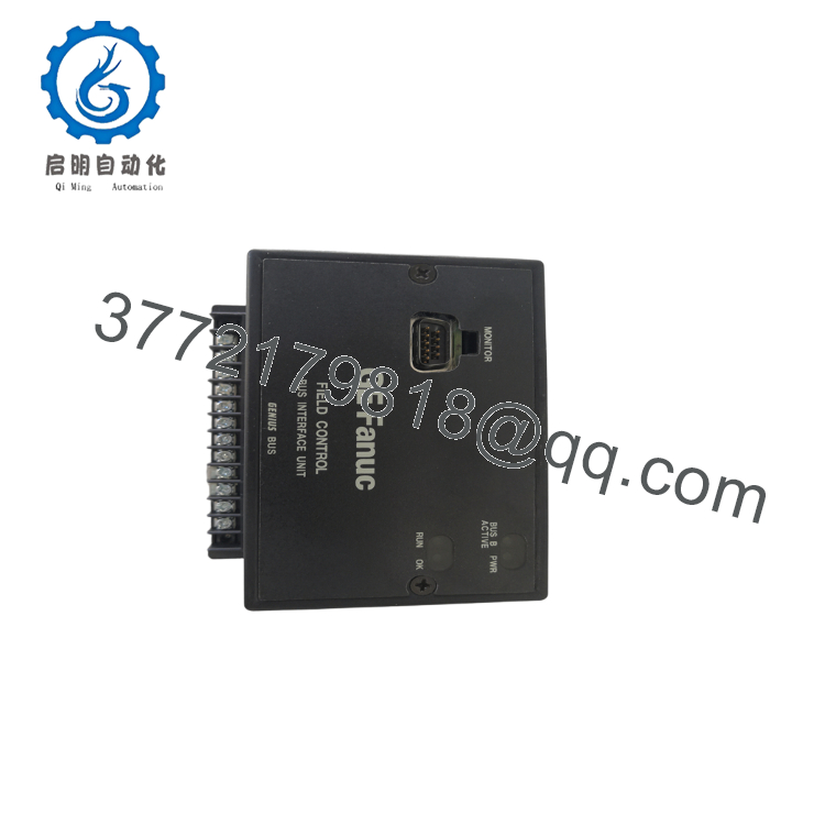
| Model | IC670GBI102D |
| Product Type | Genius Bus Interface Unit |
| Series | GE Field Control |
| Communication Protocol | Genius Bus |
| Supported I/O | Up to 8 Field Control I/O modules |
| Data Exchange | 128 Bytes Input / 128 Bytes Output |
| Power Supply | 115 VAC or 125 VDC (nominal) |
| Input Frequency | 47–63 Hz (AC operation) |
| Network Support | Single Bus or Dual Bus Redundancy |
| Connector | Genius Bus Interface Connector |
| Operating Application | Distributed I/O Interface for PLC Systems |
The IC670GBI102D serves as the communication gateway between a GE PLC or host controller and GE Field Control distributed I/O stations. It supports Genius Bus redundancy and deterministic data exchange for industrial automation applications.
4. Product Introduction
The GE IC670GBI102D is a Genius Bus Interface Unit designed for the GE Field Control distributed I/O platform. It manages communication between the host PLC and remote Field Control I/O modules over the Genius Bus network, making it suitable for manufacturing, power generation, water treatment, and process automation systems.
Engineers continue to specify this module because it supports redundant Genius Bus configurations, deterministic I/O communication, and straightforward integration with existing GE Fanuc control systems. It is especially valuable when maintaining legacy installations where minimizing downtime is more important than performing a complete control system migration.

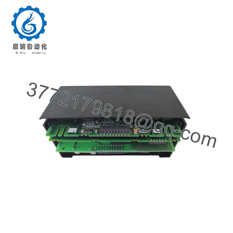
- IC670GBI102D
- IC670GBI102D
5. Installation & Configuration Guide
Stage 1 – Pre-Installation Preparation (10 minutes)
⚠️ Safety First
- Notify plant operations of scheduled downtime.
- Perform Lock-Out/Tag-Out (LOTO).
- Remove system power.
- Wait at least 5 minutes for stored energy to discharge.
Tools Required
- ESD wrist strap
- PH1 screwdriver
- Digital multimeter
- Wire labels
- Smartphone or camera
- Laptop with GE configuration software
Data Backup
- Backup PLC configuration.
- Record Genius Bus addresses.
- Photograph all wiring connections.
- Photograph jumper or switch settings before removal.
Stage 2 – Removing the Old Module (5 minutes)
- Remove the protective cover.
- Label every cable before disconnecting.
- Disconnect the Genius Bus wiring carefully.
- Release the retaining mechanism.
- Pull the module straight out without twisting.
- Inspect the backplane connector for contamination or bent pins.
⚠️ Keep the old module until commissioning has been completed successfully.
Stage 3 – Installing the New Module (10 minutes)
- Wear an ESD wrist strap.
- Verify that the replacement is IC670GBI102D.
- Copy all jumper and address settings from the original module.
- Insert the module until fully seated.
- Secure the retaining clips.
- Reconnect all wiring according to the photographs.
Installation Checklist
- ✅ Model number verified
- ✅ Address configuration matches
- ✅ Wiring confirmed
- ✅ Module fully seated
- ✅ Locking tabs secured
Stage 4 – Power-On & Testing (10 minutes)
Before Applying Power
- Measure the supply voltage.
- Check for shorts on the power terminals.
Commissioning
- Apply power to the rack.
- Verify the LED startup sequence.
- Confirm Genius Bus communication.
- Verify all connected I/O modules appear online.
- Test field inputs and outputs.
- Return the process to normal operation.
⚠️ Troubleshooting
- Solid Fault LED: Check firmware compatibility and configuration.
- No Genius Bus communication: Verify node address, bus termination, and cable polarity.
- Missing I/O modules: Inspect Genius Bus wiring and network redundancy configuration.
6. Frequently Asked Questions (FAQ)
Q1. Can I hot-swap the IC670GBI102D?
Generally, no. Unless your specific Field Control system documentation explicitly supports hot insertion, remove power before replacing the module. Hot-swapping can interrupt the Genius Bus and may damage hardware.
Q2. Is the IC670GBI102D obsolete?
Yes. The GE Field Control family is considered a legacy platform. New surplus inventory is still available from specialized industrial automation suppliers, but availability is becoming more limited.
Q3. Does replacing the Bus Interface Unit erase my PLC program?
No. The PLC program resides in the controller, not in the Bus Interface Unit. However, always back up the project and record the existing communication settings before replacement.
Q4. Does this module support redundant Genius Bus networks?
Yes. The IC670GBI102D supports both single and dual Genius Bus configurations and can operate in redundant network architectures when the overall system is configured accordingly.
Q5. Why is firmware compatibility important?
Although the hardware may be identical, firmware revisions can affect communication behavior. Before installation, document the existing revision and verify compatibility with your PLC and engineering software.
Q6. Why are New Surplus units often less expensive than OEM factory pricing?
New Surplus modules are genuine unused inventory that has remained in distribution channels after production ended. They are typically unused but may no longer be supplied directly by the original manufacturer. Always verify the module’s condition, revision level, and warranty before purchase.
Q7. What quality inspections should be completed before shipment?
A professional inspection process should include:
- OEM label and serial number verification
- Visual inspection for corrosion, scratches, or repair marks
- Functional testing on a compatible GE Field Control test rack
- Power-on verification and Genius Bus communication testing
- Insulation resistance measurement
- Documentation of hardware revision
- ESD-safe packaging with anti-static protection
- QC inspection record with shipment date
Requesting test photos or communication test videos before shipment is a practical way to verify the module’s condition, particularly for legacy automation equipment.



