
 WhatsApp: +86 16626708626
 Email:
  Phone: +86 16626708626
Description
3. Key Technical Specifications
| Parameter | Value |
|---|---|
| Manufacturer | GE Fanuc (Emerson Automation) |
| Model | IC693CHS398 |
| Product Type | Expansion Baseplate |
| PLC Family | Series 90-30 |
| Available Slots | 5 I/O slots + 1 dedicated power supply slot |
| CPU Installation | Not supported |
| Expansion Connector | 25-pin female D-type |
| Rack Address | DIP switch selectable |
| Maximum Expansion Cable Length | 50 ft (15 m) |
| Maximum Expansion Baseplates | Up to 4 (CPU331/340/341); Up to 7 (CPU350 and higher) |
| Supported Modules | Standard Series 90-30 I/O and most option modules |
| Unsupported Modules | PCM, ADC, BEM330, CMM311 (must be installed in CPU baseplate) |
| Mounting | Panel-mounted |
| Grounding | Common system ground required |
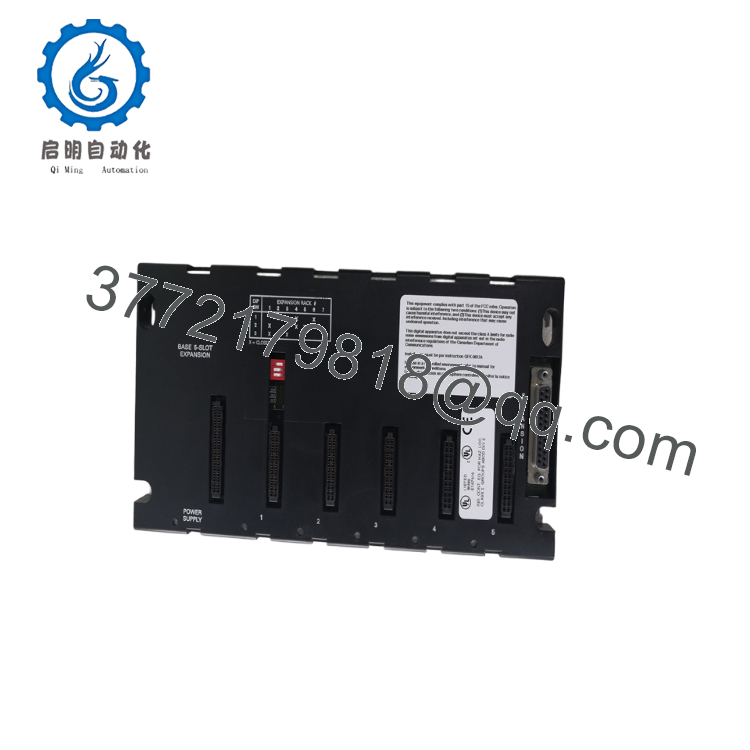
The IC693CHS398 is a 5-slot expansion baseplate for the GE Fanuc Series 90-30 PLC. It extends the local I/O system by connecting to a CPU baseplate through the Series 90-30 expansion bus. The baseplate cannot operate independently and requires connection to a CPU baseplate.
4. Product Introduction
The GE IC693CHS398 is a five-slot expansion baseplate engineered for Series 90-30 PLC systems that require additional I/O capacity beyond the primary CPU rack. It accommodates a dedicated power supply and five I/O or option modules while communicating with the CPU through the local expansion bus.
This baseplate is widely used in manufacturing, water treatment, packaging, and utility applications where existing Series 90-30 installations remain in service. Its straightforward rack addressing, compatibility with standard I/O modules, and reliable backplane architecture make it a practical solution for maintaining legacy GE Fanuc automation systems.

- IC693CHS398
5. Installation & Configuration Guide
Stage 1 – Pre-Installation Preparation (10 Minutes)
⚠️ Safety First
- Notify plant personnel of scheduled downtime.
- Perform Lock-Out/Tag-Out (LOTO).
- Remove power from the PLC system.
- Wait at least 5 minutes before servicing the rack.
Tools Required
- ESD wrist strap
- Phillips screwdriver
- Digital multimeter
- Wire labels
- Smartphone for wiring documentation
Data Backup
- Save the PLC project.
- Record the rack number.
- Photograph the expansion cable connections.
- Document module slot assignments.
Stage 2 – Removing the Existing Baseplate (10 Minutes)
- Disconnect field wiring from installed modules.
- Remove the expansion cable.
- Remove installed I/O modules if required.
- Unscrew the panel mounting hardware.
- Lift the baseplate away carefully.
- Inspect the backplane and connector for contamination or bent contacts.
⚠️ Retain the original baseplate until the replacement has completed commissioning successfully.
Stage 3 – Installing the New Baseplate (15 Minutes)
- Wear a grounded ESD wrist strap.
- Confirm the replacement part number is IC693CHS398.
- Mount the baseplate securely.
- Set the Rack Number DIP switch to match the original configuration.
- Install the power supply and I/O modules in their original slots.
- Connect and secure the 25-pin expansion cable.
Installation Checklist
- ✅ Correct model verified
- ✅ Rack number matches original
- ✅ Expansion cable secured
- ✅ Modules fully seated
- ✅ Ground connection verified
Stage 4 – Power-On & Functional Testing (10 Minutes)
Pre-Power Checks
- Verify the power supply output.
- Confirm the expansion cable is fully connected.
- Check chassis grounding continuity.
Commissioning
- Apply power to the CPU baseplate.
- Verify CPU startup completes normally.
- Confirm the expansion rack is recognized.
- Verify every installed I/O module appears online.
- Perform functional testing of representative inputs and outputs.
- Return the equipment to normal operation.
⚠️ Troubleshooting
- Expansion rack not detected: Verify the Rack Number DIP switch.
- I/O modules offline: Check module seating and expansion cable connections.
- Intermittent communication: Inspect the 25-pin expansion cable and ensure the total cable length does not exceed 50 ft (15 m).
- Option module errors: Remember that PCM, ADC, BEM330, and CMM311 modules must be installed in the CPU baseplate rather than an expansion baseplate.
6. Frequently Asked Questions (FAQ)
Q1. Can the IC693CHS398 operate without a CPU?
No. The IC693CHS398 is an expansion baseplate only. It must be connected to a Series 90-30 CPU baseplate through the expansion bus and cannot function as a standalone rack.
Q2. How many expansion baseplates can one PLC support?
The supported quantity depends on the installed CPU:
- CPU331, CPU340, CPU341: Up to 4 expansion baseplates
- CPU350 and later CPUs: Up to 7 expansion baseplates
Always verify the CPU model before expanding the system.
Q3. Can every Series 90-30 module be installed in this expansion baseplate?
No. Standard I/O modules are supported, but intelligent modules such as PCM, ADC, BEM330, and CMM311 must be installed in the CPU baseplate. Installing them in an expansion rack will prevent proper operation.
Q4. Is the IC693CHS398 still manufactured?
No. The IC693CHS398 is a discontinued Series 90-30 product. Current availability is generally limited to New Surplus inventory and professionally refurbished units.
Q5. What is the most common installation mistake?
The most common issue is configuring the wrong Rack Number DIP switch. If two expansion racks share the same address, the CPU will not recognize the system correctly. Before removing the original rack, photograph the DIP switch settings. This simple step prevents many startup delays.
Q6. Will replacing the baseplate erase my PLC program?
No. The PLC application resides in the CPU. Replacing the expansion baseplate does not affect the user program, provided the modules are reinstalled in the correct slots and the rack address remains unchanged.
Q7. What inspections should be completed before shipment?
A thorough quality inspection should include:
- OEM part number and serial number verification
- Visual inspection for corrosion, cracks, or repair marks
- Backplane connector inspection
- Rack address switch verification
- Functional testing using a genuine Series 90-30 CPU rack
- Expansion bus communication verification
- ESD-safe packaging with anti-static protection
- Final QC inspection report
For legacy Series 90-30 equipment, requesting a power-on test report and expansion communication verification before shipment is recommended to minimize installation risk.



