
 WhatsApp: +86 16626708626
 Email:
  Phone: +86 16626708626
Description
3. Key Technical Specifications
| Parameter | Value |
|---|---|
| Manufacturer | GE Fanuc (Emerson Automation) |
| Model | IC693MDL730 |
| Product Type | Positive Logic DC Output Module |
| PLC Series | Series 90-30 |
| Number of Outputs | 8 (single output group) |
| Rated Output Voltage | 12/24 VDC |
| Output Voltage Range | 12 to 24 VDC (+20%, −15%) |
| Output Type | Positive Logic (Sourcing) |
| Maximum Output Current | 2 A per point |
| Fuse Protection | Two 5 A fuses (4 outputs per fuse) |
| Isolation | 1,500 VAC between field and logic circuits |
| Inrush Current | 9.4 A for 10 ms |
| Output Voltage Drop | 1.2 V maximum |
| Off-State Leakage | 1 mA maximum |
| Response Time | 2 ms ON / 2 ms OFF |
| Backplane Current | 55 mA @ 5 VDC (all outputs ON) |
| Compatible Baseplates | Any Series 90-30 5-slot or 10-slot I/O baseplate |
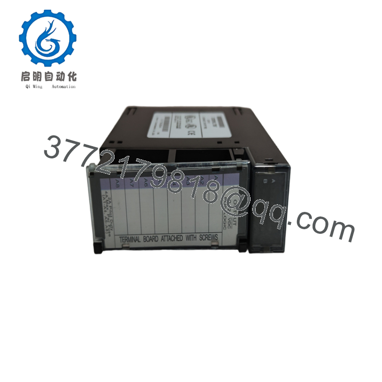
The IC693MDL730 is an 8-point positive logic DC output module for the GE Series 90-30 PLC family. It supplies current from the positive power bus to external loads such as motor starters, solenoid valves, pilot lights, and interposing relays. An external DC power supply is required for field devices.
4. Product Introduction
The GE IC693MDL730 is an 8-channel positive logic discrete output module designed for the Series 90-30 PLC platform. It converts PLC control signals into 12/24 VDC sourcing outputs for industrial field devices in manufacturing, packaging, water treatment, and material handling applications.
Each output delivers up to 2 A, making the module suitable for higher-current DC loads than standard 0.5 A output modules. Two onboard 5 A fuses protect the output circuits, while LED indicators provide immediate channel status during commissioning and troubleshooting.

- IC693MDL730
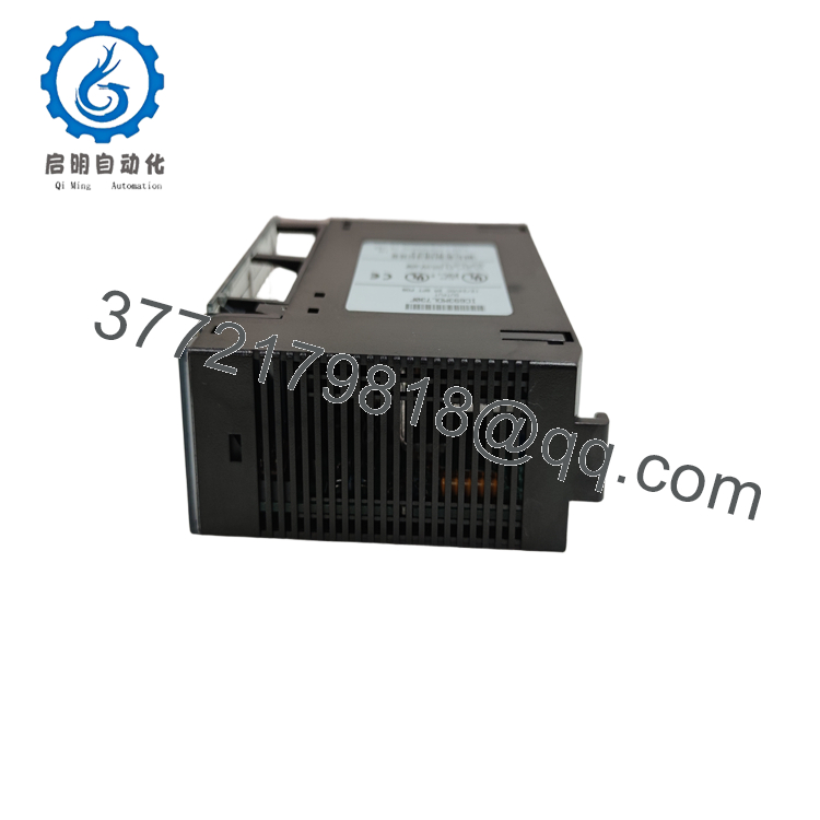
- IC693MDL730
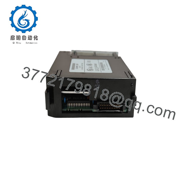
- IC693MDL730
5. Installation & Configuration Guide
Stage 1 – Pre-Installation Preparation (10 Minutes)
⚠️ Safety First
- Notify plant personnel of the scheduled shutdown.
- Perform Lock-Out/Tag-Out (LOTO).
- Turn OFF PLC and field power.
- Wait at least 5 minutes before removing the module.
Tools Required
- Grounded ESD wrist strap
- Phillips screwdriver
- Digital multimeter
- Wire labels
- Smartphone for wiring documentation
Data Backup
- Save the PLC project.
- Photograph field wiring.
- Label each output conductor.
- Record output addresses before removal.
Stage 2 – Removing the Existing Module (5 Minutes)
- Disconnect the external 12/24 VDC supply.
- Remove all field wiring.
- Release the module retaining clip.
- Pull the module straight from the baseplate.
- Inspect the connector for bent pins or contamination.
⚠️ Keep the original module until every output has been verified after startup.
Stage 3 – Installing the Replacement Module (10 Minutes)
- Wear a grounded ESD wrist strap.
- Verify the replacement part number is IC693MDL730.
- Insert the module firmly into the baseplate.
- Reconnect the field wiring according to the wiring diagram.
- Verify both onboard 5 A fuses are installed and undamaged.
- Confirm external DC polarity before energizing the system.
Installation Checklist
- ✅ Correct module installed
- ✅ Wiring polarity verified
- ✅ Fuses intact
- ✅ Module fully seated
- ✅ External power supply connected correctly
Stage 4 – Power-On & Functional Testing (10 Minutes)
Pre-Power Checks
- Measure the external 12/24 VDC supply.
- Check for shorts between output terminals.
- Verify proper grounding.
Commissioning
- Power the PLC rack.
- Apply external DC power.
- Verify channel LEDs.
- Force each output individually from the programming software.
- Confirm proper operation of connected field devices.
- Return the machine to automatic operation.
⚠️ Troubleshooting
- No outputs operate: Verify external DC supply and common wiring.
- Fuse LED illuminated: Inspect the appropriate 5 A fuse and connected load.
- Individual output inactive: Check field wiring and output transistor.
- Output remains ON: Verify PLC logic and field wiring for short circuits.
6. Frequently Asked Questions (FAQ)
Q1. Is the IC693MDL730 a sourcing or sinking output module?
The IC693MDL730 is a positive logic (sourcing) output module. It supplies current from the positive DC supply to the field device, so the load is typically connected between the output terminal and the negative power bus.
Q2. What types of field devices can it drive?
It is commonly used to control:
- Solenoid valves
- Motor starter coils
- Interposing relays
- Indicator lamps
- Audible alarms
- Small DC contactors
Each output supports up to 2 A, making it suitable for higher-current DC loads than many standard PLC output modules.
Q3. Can I hot-swap the IC693MDL730?
No. Series 90-30 output modules are not intended for hot replacement. Remove system power before replacing the module to avoid damaging the backplane or unintentionally energizing field equipment.
Q4. What is the purpose of the two onboard fuses?
The module contains two 5 A fuses:
- Fuse 1 protects outputs A1–A4
- Fuse 2 protects outputs A5–A8
If one fuse opens, only the associated group of outputs is affected, simplifying fault isolation during maintenance.
Q5. Is the IC693MDL730 still available?
The module has been discontinued as part of the legacy Series 90-30 product family. Most available units today are New Surplus, factory-sealed surplus inventory, or professionally tested refurbished modules.
Q6. What installation mistake causes the most commissioning delays?
The most common issue is reversing the external DC polarity or wiring the load as though it were a sinking output module. Positive logic modules source current, so always verify the wiring diagram before applying power. A few minutes spent checking polarity can prevent blown fuses and unnecessary troubleshooting.
Q7. What quality inspections should be completed before shipment?
A qualified supplier should complete:
- OEM part number and serial number verification
- Visual inspection for corrosion, scratches, and repair marks
- Verification of both onboard 5 A fuses
- Functional testing of all eight output channels
- Isolation and backplane power testing
- LED status verification
- ESD-safe packaging with anti-static protection
- Final QC inspection documentation
For legacy Series 90-30 hardware, requesting an 8-channel functional test report or a power-on demonstration video is a practical way to confirm the module’s condition before installation.



