
 WhatsApp: +86 16626708626
 Email:
  Phone: +86 16626708626
Description
3. Key Technical Specifications
| Parameter | Value |
|---|---|
| Manufacturer | GE Fanuc / Emerson Automation |
| Model Number | IC694MDL753 |
| Product Series | PACSystems RX3i |
| Module Type | Positive Logic Discrete Output Module |
| Output Channels | 32 points |
| Output Configuration | 4 isolated groups × 8 outputs |
| Rated Voltage | 12/24 VDC |
| Output Voltage Range | 10.2 to 28.8 VDC |
| Output Current | 0.5 A per point |
| Maximum Group Current | 4 A per group |
| Common Pin Current | 3 A maximum |
| Response Time | 0.5 ms maximum ON/OFF |
| Backplane Current Draw | 260 mA at 5 VDC |
| Isolation | 250 VAC continuous field-to-backplane; 1,500 VAC for 1 minute |
| Connector Type | Fujitsu FCN interface |
| Compatible Cables | IC694CBL327 / IC694CBL328 |
| Operating Temperature | 0 °C to +60 °C |
| Weight | Approximately 0.26 kg |
4. Product Introduction
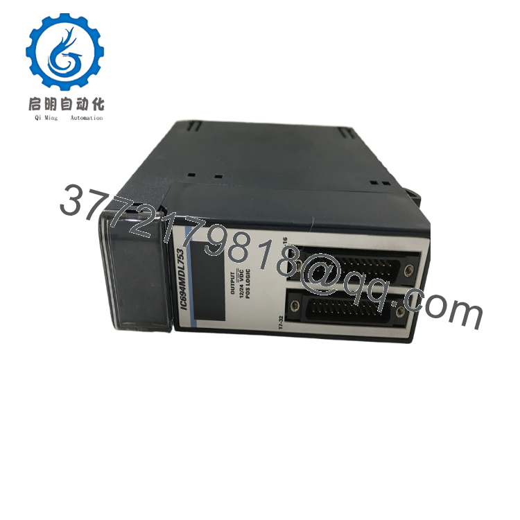
The GE Fanuc IC694MDL753 is a PACSystems RX3i 32-point positive logic discrete output module designed for 12/24 VDC field control applications. It provides four isolated groups of eight sourcing outputs and is commonly installed for solenoid valves, relay coils, indicator lamps, and other DC loads in industrial PLC panels.
The module provides 0.5 A output capability per channel, optical isolation between field wiring and the backplane, and a 0.5 ms maximum response time. It remains widely used in installed RX3i systems where maintaining existing I/O architecture is preferred over full platform migration.

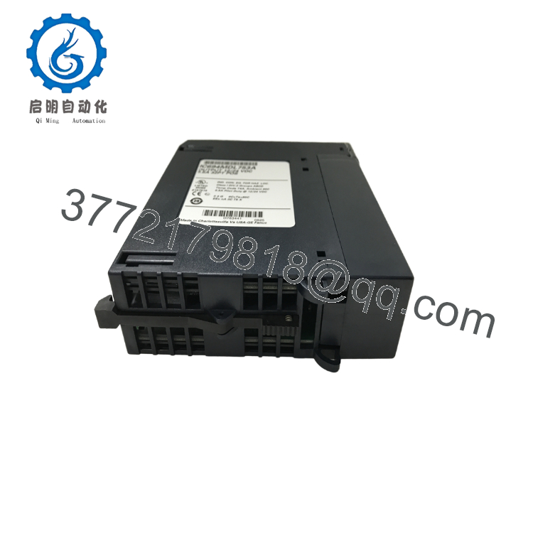
- IC694MDL753
- IC694MDL753
5. Installation & Configuration Guide
Stage 1: Pre-Installation Preparation (Estimated Time: 10 Minutes)
⚠️ Safety First
- Notify plant operations before removing the module.
- Confirm the controlled process is in a safe state.
- Apply lockout/tagout (LOTO) procedures.
- Remove rack power.
- Wait at least 5 minutes for capacitor discharge before handling the module.
Tools Required
- ESD wrist strap
- PH1 screwdriver
- Digital multimeter
- Wire labels
- Smartphone/camera for documentation
Data Backup
Before removal:
- Export the current PLC project from the programming environment.
- Record RX3i rack position and slot location.
- Photograph:
- Existing wiring
- Terminal assignments
- Connector orientation
- Any hardware identification labels
- Record CPU firmware revision and project version.
Stage 2: Removing the Old Module (Estimated Time: 5 Minutes)
- Remove the front cover or protective bezel if installed.
- Label each field connection before disconnecting.
- Disconnect the Fujitsu interface connector carefully.
- Release the module locking mechanism.
- Pull the module straight outward to protect the backplane connector pins.
- Inspect the rack slot.
Check for:
- Bent backplane pins
- Dust contamination
- Burn marks
- Loose mechanical guides
⚠️ Keep the removed IC694MDL753 until the replacement is fully tested.
The old module is often the fastest reference for wiring verification.
Stage 3: Installing the New Module (Estimated Time: 10 Minutes)
Installation Steps
- Wear an ESD wrist strap before opening packaging.
- Verify:
- Model: IC694MDL753
- Output type: 12/24 VDC Positive Logic
- Channel count: 32 points
- Compare the replacement module with the removed unit.
- Install the module:
- Align with RX3i rack guides.
- Insert evenly.
- Confirm the locking tab engages.
- Reconnect field wiring.
- Tighten connector hardware using appropriate torque.
Self-Checklist
- Correct IC694MDL753 model installed
- Connector fully seated
- Wiring labels verified
- Rack locking tab secured
- ESD precautions followed
Stage 4: Power-On & Testing (Estimated Time: 15 Minutes)
Pre-Power Check
Use a multimeter to verify:
- No short circuit on the 24 VDC supply
- Correct field supply polarity
- Proper common connections
Power-On Procedure
- Power the RX3i rack only.
- Observe module LED indicators.
- Connect programming software.
- Confirm:
- CPU communication
- Rack recognition
- Correct slot configuration
- Download the saved configuration if required.
- Perform output simulation testing.
Functional Test
Verify:
- All 32 output points
- Field device response
- Group isolation behavior
- Correct output polarity
⚠️ Troubleshooting Note
If outputs remain inactive:
- Verify the module configuration matches the PLC hardware catalog.
- Confirm the field 12/24 VDC supply is present.
- Check for wiring polarity errors.
6. Frequently Asked Questions (FAQ)
Q1: Can the GE IC694MDL753 be hot-swapped under power?
No. The IC694MDL753 should not be removed under power unless the specific RX3i rack configuration and installation documentation explicitly allow it. Removing a module from an energized rack can damage connectors or create unexpected output states. Shut down the rack and follow LOTO procedures.
Q2: Is the IC694MDL753 obsolete?
The IC694MDL753 is a legacy GE Fanuc RX3i module. Availability depends on remaining inventory from automation spare-part suppliers. Some units are New Original, New Surplus, or Refurbished (tested), so confirm condition before purchasing.
Q3: Will I lose PLC logic when replacing the IC694MDL753?
No. The IC694MDL753 stores no user program logic. The PLC CPU contains the application program. However, verify that the hardware configuration still matches the installed I/O module after replacement.
Q4: What is the direct replacement for IC694MDL753?
The correct replacement depends on the RX3i hardware configuration, output requirements, wiring method, and future migration plans. Do not substitute another output module based only on voltage rating. Verify channel count, connector type, and output architecture first.
Q5: Why is this module available below OEM list pricing?
Industrial automation spare parts often enter the secondary market after plant upgrades, system migrations, or inventory reductions. Lower pricing usually reflects sourcing channel differences, not necessarily reduced functionality. Always confirm serial number condition, testing records, and warranty coverage.
Q6: What condition should I request when buying IC694MDL753?
For critical production systems, request:
- New Original / New Surplus if available
- Serial number verification
- Functional test report
- Firmware or hardware revision record
- Warranty terms
A tested refurbished module can also be acceptable for non-critical applications if the supplier provides documented inspection results.
Q7: What common replacement mistake should engineers avoid?
The most common issue is wiring and output configuration mismatch.
I have seen technicians replace a DC output card, power up the rack, and immediately chase PLC software problems when the actual issue was a reversed field supply or incorrect connector wiring. Photograph the original installation before removal. That five-minute step prevents hours of troubleshooting.
Keep these checks in mind and you will avoid most unnecessary commissioning delays.



