
 WhatsApp: +86 16626708626
 Email:
  Phone: +86 16626708626
Description
3. Key Technical Specifications
| Parameter | Value |
|---|---|
| Manufacturer | GE Intelligent Platforms / Emerson |
| Model | IC695PSD140A |
| Product Series | PACSystems RX3i |
| Product Type | Multipurpose DC Power Supply |
| Input Voltage | 18–30 VDC (24 VDC nominal) |
| Maximum Input Power | 60 W |
| Maximum Output Power | 40 W combined |
| +5.1 VDC Output | Up to 30 W |
| +3.3 VDC Output | Up to 30 W |
| +24 VDC Relay Output | Supports relay output modules |
| Ride-Through Time | Up to 10 ms |
| Redundancy Support | Yes (load-sharing with up to four PSD140 units) |
| Installation | RX3i Universal Backplane |
| Operating Temperature | 0 °C to +60 °C |
The IC695PSD140A is designed for 24 VDC-powered RX3i systems and supports redundant or increased-capacity power configurations when used with compatible PSD140 modules. It must not be mixed with IC695PSD040 or IC695PSA040 in redundant configurations.
4. Product Introduction
The GE IC695PSD140A is a 24 VDC multipurpose power supply for the PACSystems RX3i platform. It converts field power into the regulated voltages required by the RX3i backplane and supplies auxiliary 24 VDC power for compatible relay output modules. It is widely deployed in process automation, manufacturing, water treatment, and utility control systems.
Unlike a simple rack power supply, the IC695PSD140A supports load-sharing and redundant power architectures, making it suitable for applications where controller availability is a priority. When replacing an early Revision A unit, review the hardware revision history because later revisions addressed startup behavior and electromagnetic compatibility without changing the installation footprint.
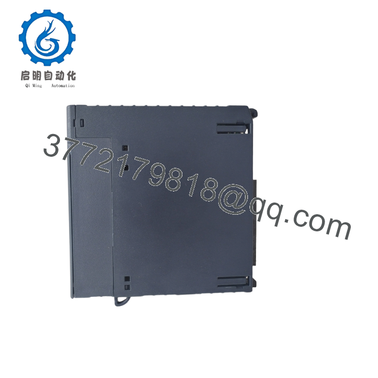
- IC695PSD140A
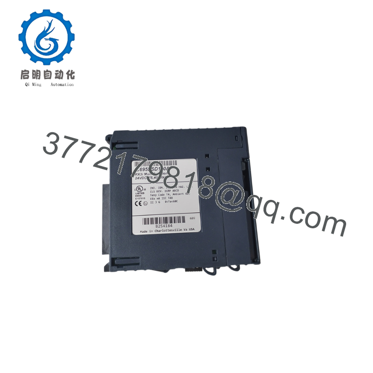
- IC695PSD140A
5. Installation & Configuration Guide
Stage 1 – Pre-Installation Preparation (10 Minutes)
⚠️ Safety First
- Notify operations before shutting down the controller.
- Bring the process to a safe operating condition.
- Apply Lockout/Tagout procedures.
- Disconnect the external 24 VDC supply.
- Wait at least 5 minutes for internal capacitors to discharge.
Tools Required
- Grounded ESD wrist strap
- PH1 screwdriver
- Fluke 115 (or equivalent) digital multimeter
- Wire labels
- Smartphone for documentation
Data Backup
Before removing the power supply:
- Photograph all field wiring.
- Record the external power supply voltage.
- Document rack configuration.
- If redundancy is used, record the complete power-sharing arrangement.
Stage 2 – Removing the Old Module (5 Minutes)
- Verify input power is isolated.
- Label and disconnect all wiring.
- Release the retaining latch.
- Remove the module straight from the Universal Backplane.
- Inspect:
- Backplane connectors
- Terminal screws
- Wiring insulation
- Signs of overheating
⚠️ Retain the removed module until the replacement has completed load testing.
Stage 3 – Installing the New Module (10 Minutes)
- Wear a grounded ESD wrist strap.
- Verify the catalog number:
IC695PSD140A
- Confirm the replacement matches the system design.
- Insert the module until fully seated.
- Secure the retaining mechanism.
- Reconnect the 24 VDC input wiring.
- Verify polarity before energizing.
Installation Checklist
- Correct model verified
- Wiring polarity confirmed
- Backplane connector fully seated
- Mounting secured
- Redundancy wiring verified (if applicable)
Stage 4 – Power-On & Functional Testing (15 Minutes)
Pre-Power Checks
- Verify the incoming supply is between 18 VDC and 30 VDC.
- Check for shorts between positive and negative conductors.
- Confirm protective earth continuity.
- Verify all terminal screws are tightened correctly.
Startup Procedure
- Apply 24 VDC input power.
- Observe power supply indicators.
- Verify CPU startup.
- Confirm all installed I/O modules initialize normally.
- Measure:
- +5.1 VDC
- +3.3 VDC
- +24 VDC relay supply
- Perform a controlled I/O functional test.
⚠️ Troubleshooting
If the CPU reports a Power Supply Fault:
- Verify input voltage remains within specification under load.
- Inspect the backplane connector.
- Check total rack power consumption.
- If using redundant supplies, verify correct load-sharing connections.
Technical Pitfalls & Survival Guide
❗ Hardware Revision Matters
I’ve seen maintenance teams replace a failed Revision D supply with an original Revision A from storage without checking the service history.
The controller started, but intermittent startup faults returned. GE released later revisions to improve startup reliability and EMC immunity while keeping the same installation dimensions. If you’re replacing an early Revision A unit, consider whether a newer revision is acceptable for your site standard.
❗ Don’t Mix Different Power Supply Families
This catches people more often than you’d expect.
The IC695PSD140 family is designed for redundant and load-sharing applications. It should not be combined with IC695PSD040 or IC695PSA040 in redundant configurations. The hardware may fit, but the power architecture is different.
❗ Verify Rack Power Budget
Don’t size the power supply based only on today’s configuration.
I’ve seen a rack work perfectly during commissioning, then fail months later after additional analog modules were installed. Calculate the total 5 VDC and 3.3 VDC demand and maintain at least a 20% capacity margin.
❗ Input Power Quality
A stable 24 VDC source is just as important as the power supply itself.
Voltage sag, loose terminals, or undersized conductors can trigger intermittent power faults that resemble CPU failures. Measure the input voltage while the rack is fully loaded, not just at idle.
❗ Electrostatic Discharge (ESD)
Even though it’s a power supply, treat it like any other electronic module.
Always wear a grounded wrist strap and work on an ESD-safe surface. Static damage isn’t always immediate—it can reduce long-term reliability.
Keep these checks in mind and you’ll avoid most of the startup and power-related issues that extend maintenance outages.
6. Frequently Asked Questions (FAQ)
Q1. Can the IC695PSD140A be replaced while the rack is energized?
No.
Disconnect the external 24 VDC source before replacing the module. Removing a power supply under load can interrupt the entire controller and may damage connected equipment.
Q2. What input voltage does the IC695PSD140A require?
The module operates from 18 VDC to 30 VDC, with 24 VDC nominal. Verify the voltage under full load, not just with a no-load measurement.
Q3. Can this power supply be used in redundant systems?
Yes.
The IC695PSD140 family supports load-sharing and redundancy with compatible PSD140 modules installed in an RX3i Universal Backplane. Do not mix it with PSD040 or PSA040 power supplies in redundant configurations.
Q4. Is Revision A interchangeable with later revisions?
Generally, yes.
Later revisions (B through E) retained the same form, fit, and functionality while addressing startup reliability, surge immunity, and regulatory updates. Review your site’s change-control requirements before substituting revisions.
Q5. Why is a New Surplus unit often less expensive than OEM pricing?
New Surplus inventory typically comes from canceled projects, spare-part stock reductions, or unused system inventories. Although unused, these modules may not include the original manufacturer’s warranty. Request serial number verification, inspection records, and functional test documentation before purchase.
Q6. What quality inspections should be completed before shipment?
For production-critical systems, request documentation covering:
- OEM serial number verification
- Visual inspection for corrosion, scratches, or repair marks
- Functional testing on a genuine RX3i Universal Backplane
- Output voltage verification (+5.1 VDC, +3.3 VDC, and +24 VDC relay output)
- Continuous load testing for at least 24 hours
- Insulation resistance testing (>10 MΩ at 500 V where applicable)
- ESD-safe packaging with QC sign-off
Test photographs and load-test reports are particularly valuable when replacing a power supply during a scheduled plant shutdown.



