
 WhatsApp: +86 16626708626
 Email:
  Phone: +86 16626708626
Description
3. Key Technical Specifications
| Parameter | Value |
|---|---|
| Manufacturer | GE Fanuc / Emerson |
| Model | IC697BEM731 |
| Product Series | Series 90-70 |
| Module Type | Genius Bus Controller |
| Communication Channels | 1 Genius Bus Channel |
| Maximum Devices | 30 Genius devices per channel |
| Supported Data Rates | 38.4, 76.8, 153.6 Kbaud (Standard/Extended) |
| Hand-Held Monitor Port | 1 |
| Backplane Current | 1.3 A @ 5 VDC |
| Bus Cable | Belden 9182 or equivalent |
| Maximum Cable Length | 2,000–7,500 ft (depends on baud rate) |
| Bus Termination | 75 Ω or 150 Ω terminators |
| Installation | Single slot in Series 90-70 rack |
| Operating Temperature | Refer to Series 90-70 installation specifications |
The IC697BEM731 is a single-channel Genius Bus Controller for the Series 90-70 PLC. It supports one Genius network with up to 30 distributed devices and multiple selectable communication speeds.
4. Product Introduction
The GE IC697BEM731 is a Genius Bus Controller Module designed for the Series 90-70 PLC platform. It manages communication between the PLC CPU and remote Genius I/O devices, including IC660 and IC661 distributed I/O blocks. The module occupies one rack slot and exchanges I/O data asynchronously with the controller over the Series 90-70 backplane.
The module supports redundant Genius architectures, peer communications, and CPU-directed messaging. Although the Series 90-70 platform is now considered a legacy control system, the IC697BEM731 remains widely used in power generation, water treatment, metals, chemical processing, and manufacturing facilities where Genius I/O networks continue to operate reliably.
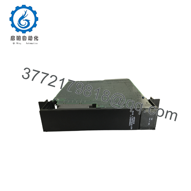
- IC697BEM731
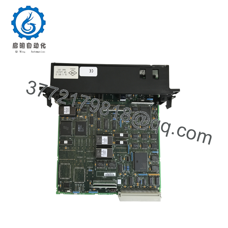
- IC697BEM731
5. Installation & Configuration Guide
Stage 1 – Pre-Installation Preparation (10 Minutes)
⚠️ Safety First
- Notify plant operations of the planned outage.
- Place the controlled equipment into a safe operating condition.
- Apply Lockout/Tagout procedures.
- Remove power from the Series 90-70 rack.
- Wait at least 5 minutes before removing electronic modules.
Tools Required
- Grounded ESD wrist strap
- PH1 screwdriver
- Fluke 115 digital multimeter
- Wire identification labels
- Laptop with GE Logicmaster or Proficy software
- Smartphone for documentation
Data Backup
Before removing the module:
- Save the PLC hardware configuration.
- Record the Genius bus baud rate.
- Document all device addresses.
- Photograph cable routing.
- Record CPU firmware revision.
Stage 2 – Removing the Existing Module (5 Minutes)
- Disconnect rack power.
- Disconnect the Genius bus connector.
- Label all communication cables.
- Release the retaining mechanism.
- Remove the module straight from the backplane.
Inspect:
- Backplane connector
- Bus connector
- Shield termination
- Evidence of overheating
⚠️ Keep the original module until the replacement network has been fully commissioned.
Stage 3 – Installing the New Module (10 Minutes)
- Wear a grounded ESD wrist strap.
- Verify the replacement catalog number:
IC697BEM731
- Confirm the module matches the configured Genius network.
- Insert the module completely into the rack.
- Lock the retaining mechanism.
- Connect the Genius cable.
- Verify proper bus termination at both ends of the network.
Installation Checklist
- Correct catalog number
- Bus connector secured
- Shield grounded correctly
- Bus terminators installed
- Rack connector fully seated
Stage 4 – Power-On & Communication Testing (15–20 Minutes)
Pre-Power Checks
- Verify 5 VDC backplane power.
- Measure Genius cable continuity.
- Verify termination resistors.
- Confirm no duplicate device addresses.
Startup Procedure
- Energize the PLC rack.
- Observe the module LEDs.
- Confirm the CPU recognizes the Bus Controller.
- Verify communication with all Genius devices.
- Perform an I/O scan test.
- Confirm all remote blocks report healthy status.
⚠️ Troubleshooting
If the network remains offline:
- Verify all bus termination resistors.
- Confirm baud rate consistency across every Genius device.
- Check cable polarity.
- Inspect shielding and grounding.
- Verify duplicate Genius node addresses are not present.
Technical Pitfalls & Survival Guide
❗ Baud Rate Mismatch
This remains one of the most common Genius startup failures.
I’ve seen technicians replace a Bus Controller, leave the network configured at 153.6 Kbaud, while half the remote blocks were still configured for 76.8 Kbaud. The LEDs looked normal, but no I/O updated. Always verify the configured baud rate before energizing the network.
❗ Bus Termination
Never assume the existing terminators are still correct.
Only the two physical ends of the Genius network should be terminated with the specified 75 Ω or 150 Ω resistor. Adding an extra terminator in the middle of the trunk can create intermittent communication faults that are difficult to diagnose.
❗ Device Address Duplication
Every Genius device requires a unique node address.
I’ve watched commissioning teams spend an entire shift replacing hardware when two replacement I/O blocks had identical addresses. Five minutes with a Hand-Held Monitor would have identified the problem immediately.
❗ Cable Quality
Use the specified Belden 9182 cable or an approved equivalent.
Substituting generic twisted-pair cable often results in unreliable communication, particularly on long network segments approaching the maximum supported distance.
❗ Electrostatic Discharge (ESD)
Although the module primarily handles communications, its interface circuitry remains sensitive to static discharge.
Always install the module on an ESD-safe work surface while wearing a grounded wrist strap.
Keep these checks in mind and you’ll avoid most of the communication problems that extend commissioning time.
6. Frequently Asked Questions (FAQ)
Q1. What does the IC697BEM731 do?
It serves as the Genius Bus Controller for a Series 90-70 PLC, managing communication between the CPU and Genius distributed I/O devices, including IC660 and IC661 blocks.
Q2. How many Genius devices can one IC697BEM731 support?
A single controller supports up to 30 Genius devices on one communication channel, provided network design and cable length remain within specification.
Q3. Can I replace the module without shutting down the PLC?
No.
The IC697BEM731 is not designed for hot-swapping. Remove rack power before replacing the module to avoid backplane damage and communication faults.
Q4. Is the IC697BEM731 obsolete?
Yes.
The Series 90-70 platform is a legacy GE control system. New Original inventory is limited, although New Surplus and professionally tested refurbished units remain available from industrial spare-parts suppliers. Procurement teams should verify long-term availability when planning maintenance strategies.
Q5. Why is my Genius network offline after replacing the Bus Controller?
The most common causes are:
- Incorrect Genius baud rate
- Missing or incorrect termination resistors
- Duplicate node addresses
- Cable polarity errors
- Damaged Belden 9182 communication cable
In my experience, these account for the majority of startup problems—hardware failure is much less common.
Q6. What inspections should be completed before shipment?
For production-critical applications, request:
- OEM serial number verification
- Visual inspection for corrosion, rework, or connector damage
- Functional testing on a genuine Series 90-70 rack
- Genius network communication test
- Hand-Held Monitor port verification
- 24-hour operational burn-in
- QC documentation
- ESD-safe packaging
Requesting startup photographs or communication test videos can reduce commissioning risk, especially when replacing a legacy communication module during a scheduled plant outage.



